Electrical cable wiring head device and electrical cable wiring apparatus

a technology of electrical cable and wiring head, which is applied in the direction of metal working apparatus, manufacturing tools, connections, etc., can solve the problems of significant flotation affecting the service life of electrical cables, and likely floatation of coated electrical cables so as to reduce the number of operations, effectively restrain the cable from flotation from the wiring plate, and fast connect the electrical cable

Inactive Publication Date: 2011-02-10
SUMITOMO WIRING SYST LTD
View PDF2 Cites 4 Cited by
  • Summary
  • Abstract
  • Description
  • Claims
  • Application Information

AI Technical Summary

Benefits of technology

According to the first aspect of the present invention, since the roller portion that guides the electrical cable supplied from the head section is disposed on the rotary axis of the head section, the roller portion of the guide pushing member can guide the electrical cable on the rotary axis of the head section. Thus, even when the head section is rotated about the rotary axis in order to bend and wire the electrical cable, the roller portion of the guide pushing member can guide the electrical cable. Thus, it is possible to effectively restrain the cable from floating from the wiring plate. Consequently, even if the electrical cable is bent and connected to the wiring surface, it is possible to reduce the number of operations of pushing the electrical cable when the head section is stopped, thereby rapidly connecting the electrical cable.
According to the second aspect of the electrical cable wiring head device, since the roller portion can guide the electrical cable near the wiring surface rather than the bottom surface of the head section during wiring the electrical cable, it is possible to surely prevent the electrical cable from floating from the wiring plate.
According to the third aspect of the electrical cable wiring head device, it is possible to press the electrical cable onto the wiring plate even by the auxiliary pushing member.
According to the electrical cable wiring apparatus of the fourth aspect, it is possible to more rapidly connect the electrical cable while the electrical cable is being more effectively restrained from floating from the wiring plate.

Problems solved by technology

However, according to the technique disclosed in JP-A-10-224951, because the third guide roller for guiding the coated electrical cable is disposed at the rear side from the rotary axis of the head section in the wiring direction and at the position higher than the bottom surface of the head section when the head section is moving, there is a problem that the coated electrical cable is floated from the wiring plate significantly.
Consequently, there is a problem that a period in time for wiring will be elongated.
According to the technique disclosed in JP-A-2007-53847, because it is possible to press the coated electrical cable onto the wiring plate only when the head section moves straightly along the X-axis direction or the Y-axis direction, there is a problem that the coated electrical cable is likely to float from the wiring plate at the bending point or the like.

Method used


Image

  • Electrical cable wiring head device and electrical cable wiring apparatus
  • Electrical cable wiring head device and electrical cable wiring apparatus
  • Electrical cable wiring head device and electrical cable wiring apparatus

Examples


Embodiment Construction

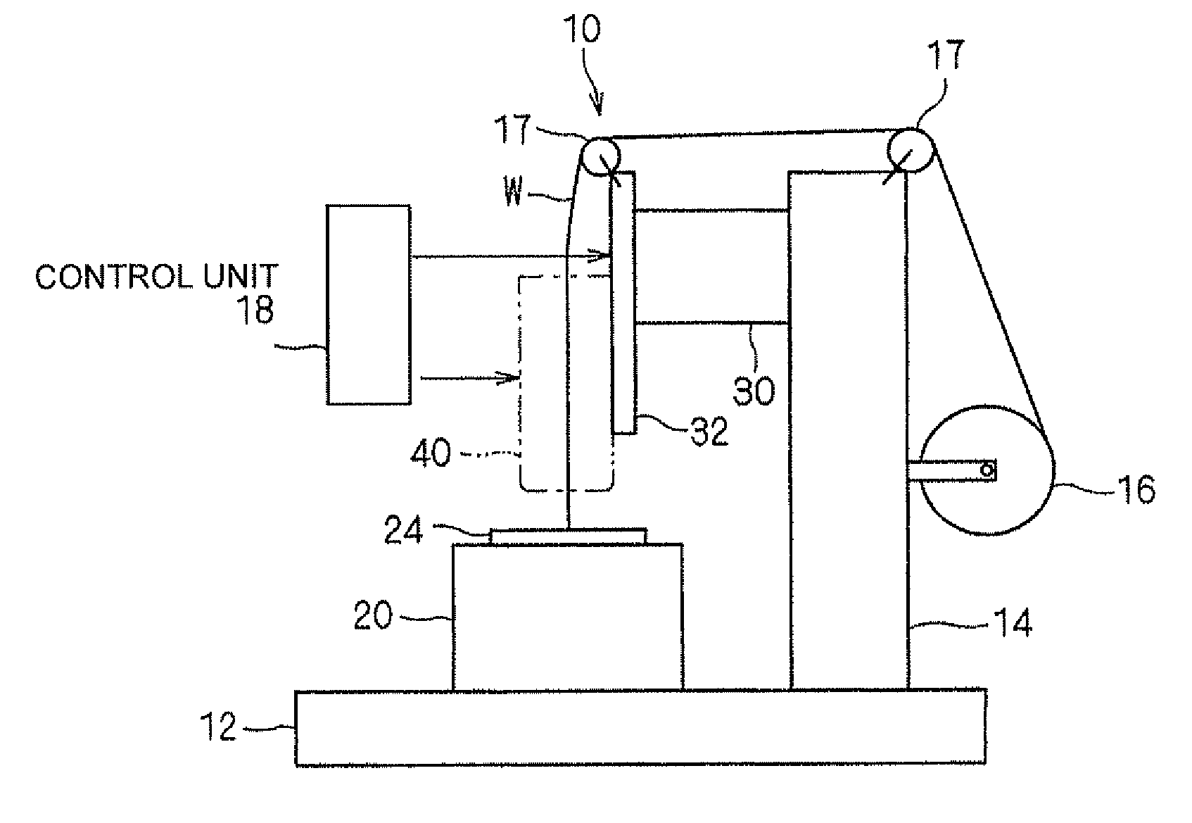
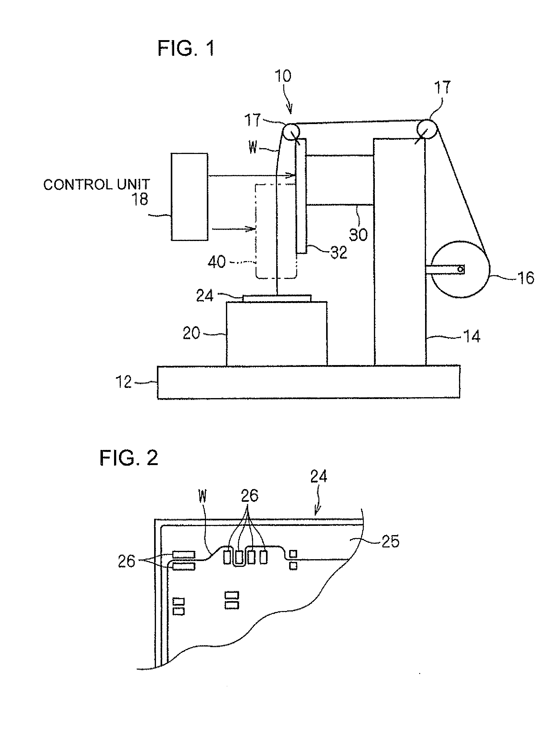
Referring now to the drawings, embodiments of an electrical cable wiring head device and an electrical cable wiring apparatus including the head device in accordance with the present invention will be described below. FIG. 1 is an explanatory view illustrating the whole of an electrical cable wiring apparatus 10. FIG. 2 is a schematic plan view illustrating a part of a wiring plate 24 that is an object to be wired.

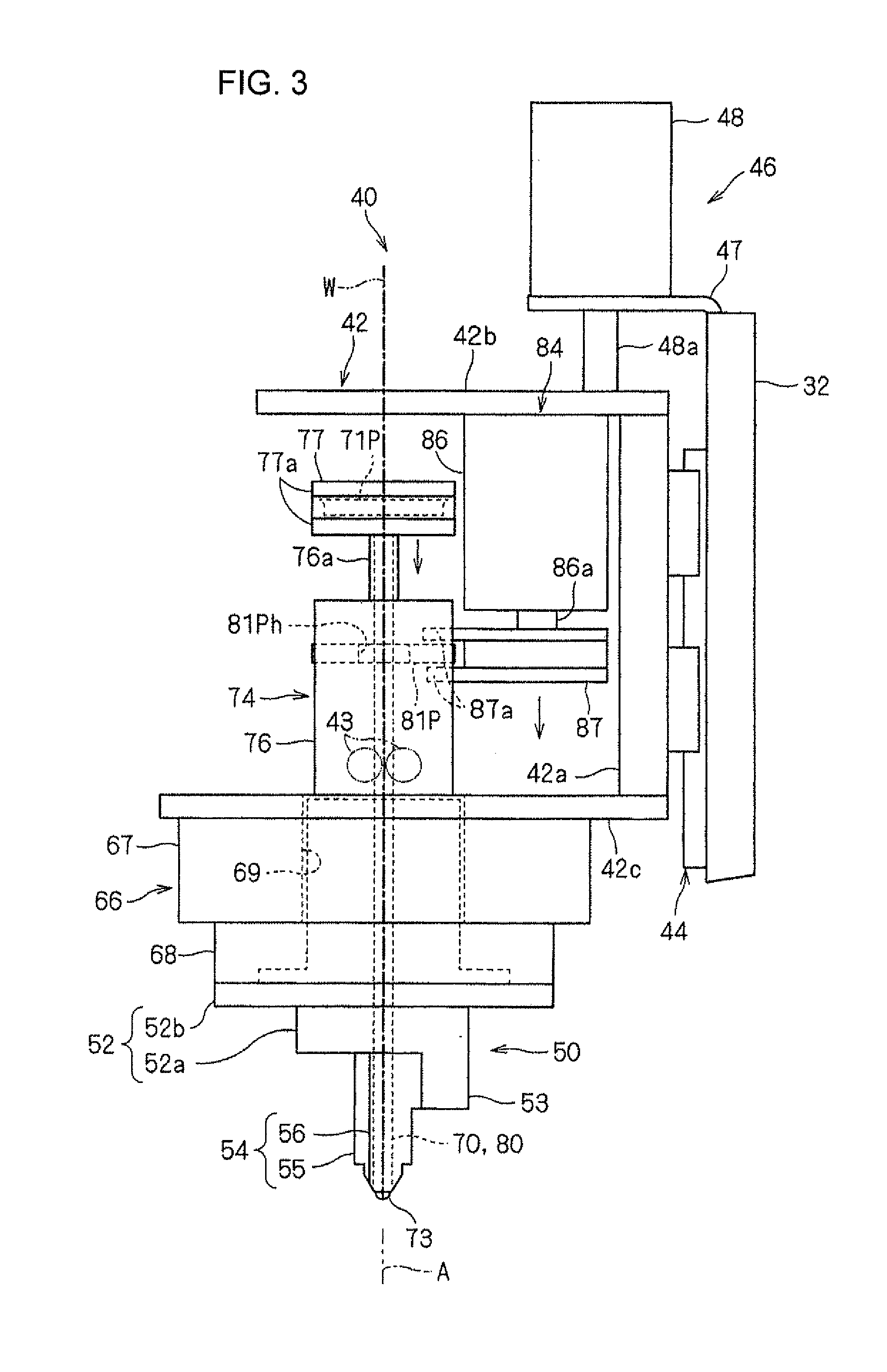
Firstly, a general whole construction of the electrical cable wiring device 10 will be described below. The electrical cable wiring device 10 includes an electrical cable wiring head device 40, a wiring plate setting section 20, and a wiring drive section 30.

The wiring plate setting section 20 serves as a wiring object holding section that holds the wiring plate 24 (an object to be wired) at a given position and in a given posture. The wiring plate setting section 20 is fixed on a given base table 12. The wiring plate 24 is held on the wiring plate setting section 20 by a ...


PUM

PropertyMeasurementUnit
angleaaaaaaaaaa
bending pointaaaaaaaaaa
timeaaaaaaaaaa

Abstract

An electrical cable wiring head apparatus is provided to rapidly wire an electrical cable while more effectively restraining the electrical cable from floating. An electrical cable wiring head device of the electrical cable wiring head apparatus moves along a wiring surface of a wiring plate to wire an electrical cable on the wiring surface. The electrical cable wiring head device comprises: a head section supported rotatably about a rotary axis and provided with a guide recess for leading the electrical cable to the wiring surface, the guide recess being offset from the rotary axis; a head rotating mechanism for rotating the head section; a guide pushing member including a shaft portion and a roller portion provided rotatably on a distal end of the shaft portion, the guide pushing member being supported movably along the rotary axis; and a guide pushing member drive mechanism for reciprocating the guide pushing member.

Description

CROSS-REFERENCE TO RELATED APPLICATIONThis, application claims priority to JP2009-182386 filed in Japan on Aug. 5, 2009, the disclosure of which is hereby incorporated by reference in its entirety.BACKGROUNDThis invention relates to a technique for producing an electrical circuit component provided with a wired electrical cable, such as an electrical junction box or the like to be used as motor vehicle parts.Electrical cable wiring apparatuses have been known in the art. For example, JP-A-10-224951 discloses an electrical cable wiring apparatus in which a head section for supplying a coated electrical cable is rotatably supported and a pushing pin and a third guide roller are incorporated with the head section. The third guide roller is disposed at a rear side from a rotary axis of the head section in a wiring direction and at a position higher than a bottom surface of the head section. When the head section is moved, the electrical cable is drawn out of the head section while the c...

Claims


Application Information

Patent Timeline
Patent Type & Authority Applications(United States)
IPC IPC(8): B23P19/00
CPCH05K13/06Y10T29/5187Y10T29/532Y10T29/53213Y10T29/53174Y10T29/53261
Inventor TANI, NORIYUKIOOISHI, AKINORI
Owner SUMITOMO WIRING SYST LTD
Why Eureka
Try Eureka