
Ballistics systems and methods

a technology of ballistics and systems, applied in the field of ballistics and guns, can solve the problems of difficulty in accurately aiming guns, and time-consuming for shooters, and achieve the effect of reducing disadvantages and problems

Active Publication Date: 2011-02-10
HUSKEMAW OPTICS
View PDF31 Cites 25 Cited by
  • Summary
  • Abstract
  • Description
  • Claims
  • Application Information

AI Technical Summary

Benefits of technology

"The patent text describes a system and method for improving the accuracy and flexibility of a scope by eliminating or reducing the disadvantages and problems associated with projectile drops. The system includes an adjustment dial that can be moved to different positions to compensate for projectile drops at different distances to a target. The dial is labeled with dial-calibration data that includes distance indicators and windage hold-off indicators. The windage hold-off indicators help compensate for deflection caused by crosswind. The system also includes an electronic device that uses a derived distance calculation module to calculate a derived distance based on the distance to the target and actual shooting conditions. This allows the scope to accurately aim at a target under different shooting conditions. Overall, the system improves the accuracy and flexibility of the scope by compensating for projectile drops and windage hold-off."

Problems solved by technology

Because accurately aiming guns may become more difficult as the distance to a target increases, scopes are often used in connection with guns.
But, even when using a scope, shooters may find it difficult and / or time consuming to accurately aim at a target.

Method used


Image

  • Ballistics systems and methods
  • Ballistics systems and methods
  • Ballistics systems and methods

Examples


Embodiment Construction

[0006]A need therefore exists for systems and / or methods that eliminate or diminish the disadvantages and problems described above.

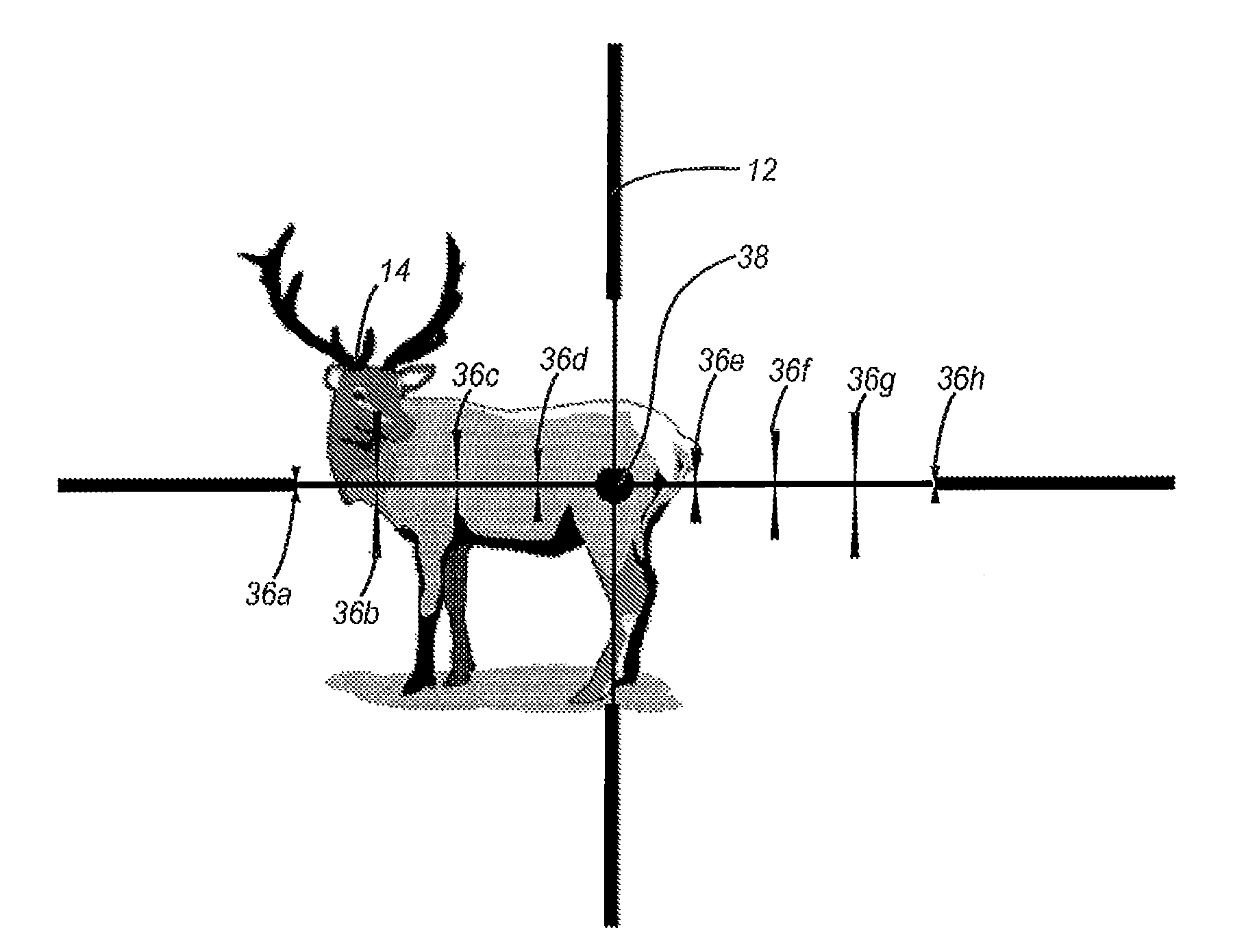
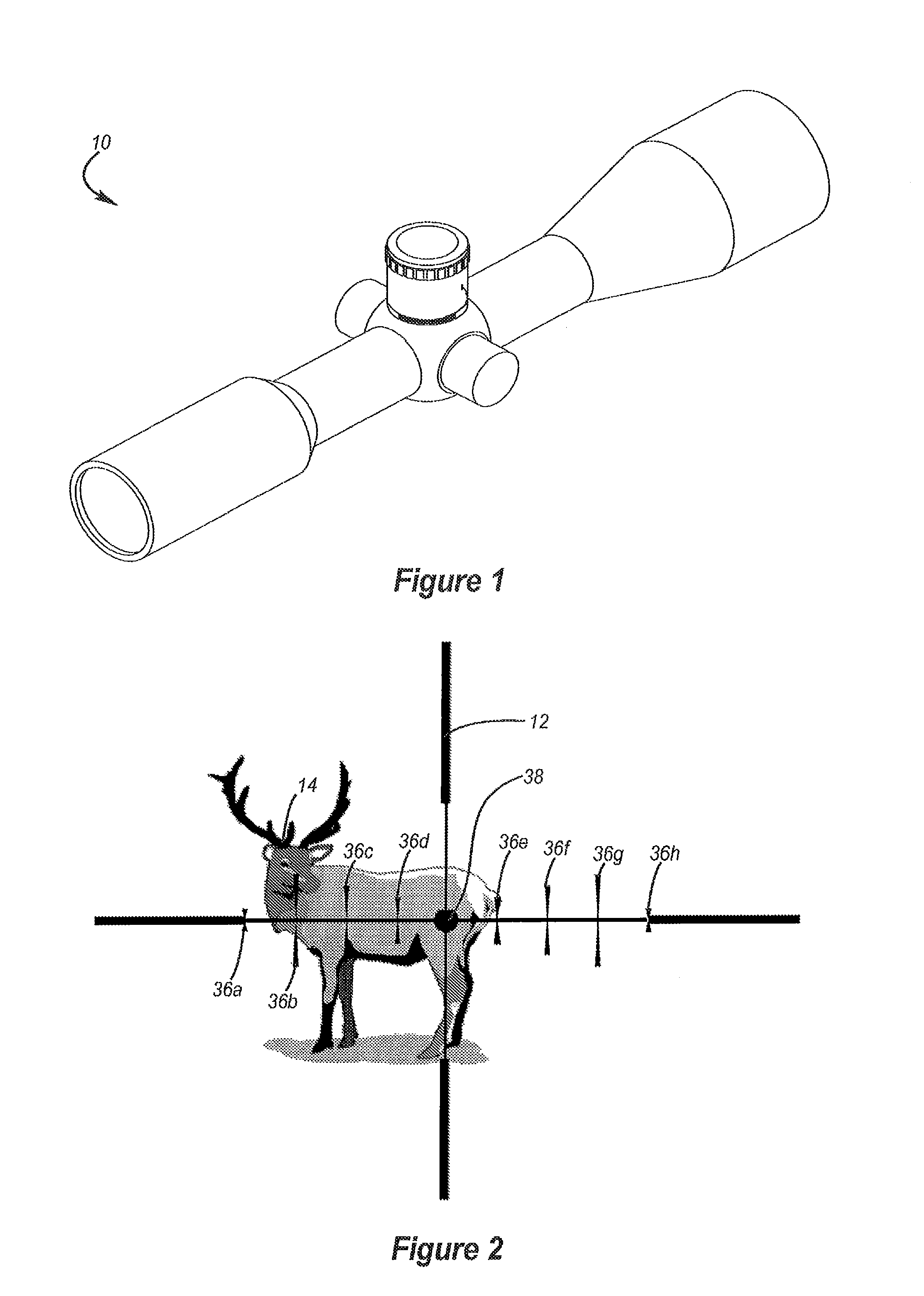
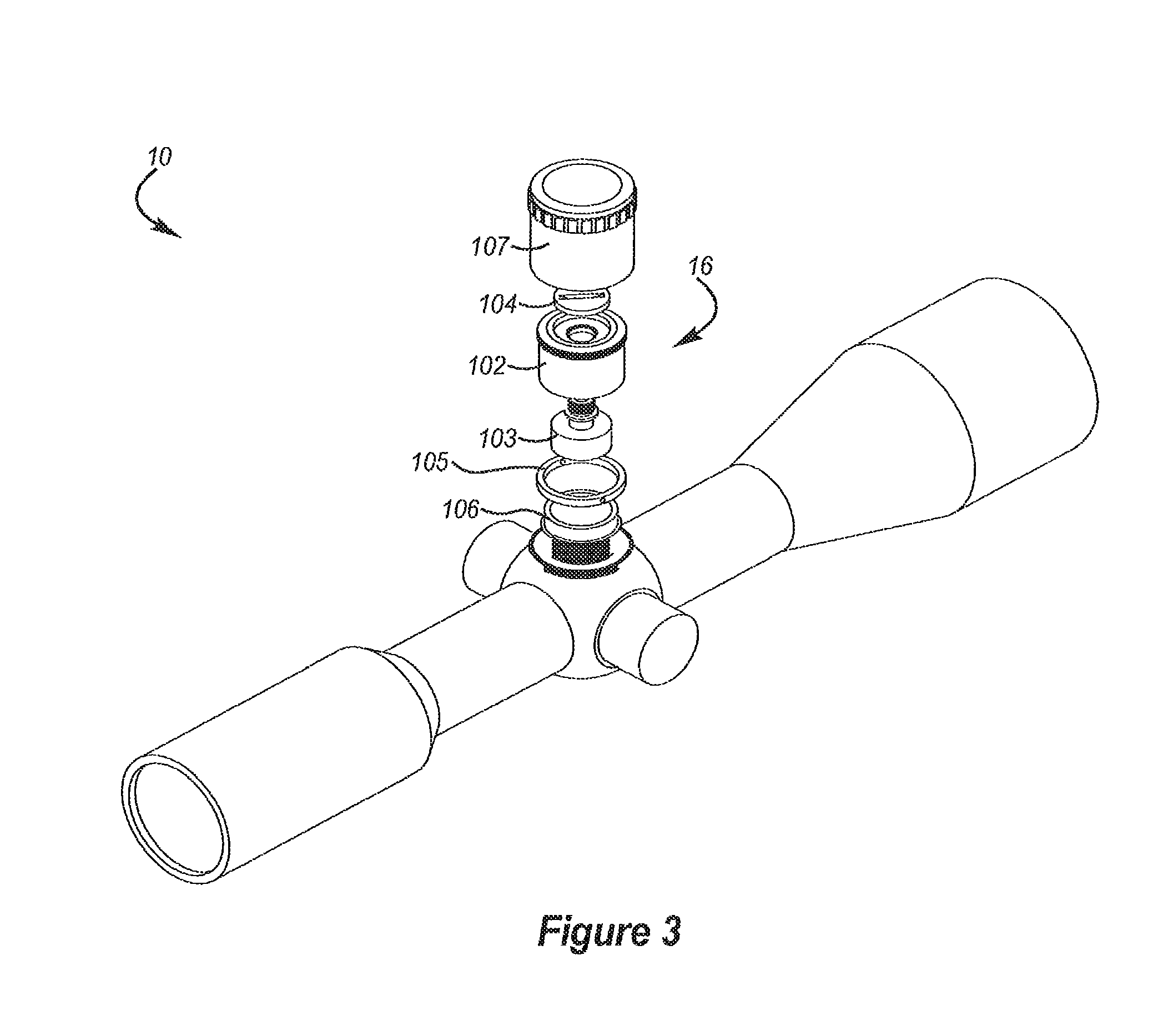
[0007]One aspect is a scope that may include an adjustment dial, which may be moved among a plurality of positions to configure the scope to compensate for projectile drops. The adjustment dial may be labeled with dial-calibration data, which may include one or more distance indicators. In particular, the adjustment dial may be sized and configured to move among a plurality of positions to configure the scope to compensate for projectile drops associated with a range of distances to a target, and the distance indicators may be configured to indicate at least some of the distances within the range. Desirably, the distance indicators may allow a shooter to quickly select a distance to a target to configure the scope to compensate for a projectile drop associated with the selected distance.

[0008]Another aspect is a scope that may include an adjustment dial ...


PUM


Abstract

A scope may include an adjustment dial, which may be moved among a plurality of positions to configure the scope to compensate for projectile drops. The adjustment dial may be labeled with dial-calibration data, which may include one or more distance indicators and / or one or more windage hold-off indicators. The scope may be attached to a gun and the dial-calibration data may be at least partially generated using ballistics performance data based on shots fired by the gun. The dial-calibration data may be at least partially generated using shooting conditions. An electronic device may include a derived distance calculation module, which may be configured to use a distance to a target and actual shooting conditions to calculate a derived distance. The derived distance may be used in connection with an adjustment dial labeled with dial-calibration data at least partially generated using shooting conditions different from the actual shooting conditions.

Description

CROSS-REFERENCE TO RELATED APPLICATIONS[0001]This application claims priority and the benefit of U.S. provisional patent application 60 / 822,289, which was filed Aug. 14, 2006 and entitled RAPID FIELD BALLISTIC COMPENSATOR AND METHOD OF PROVIDING THE SAME, the disclosure of which is incorporated by reference in its entirety.BACKGROUND OF THE INVENTION[0002]1. Field of the Invention[0003]The present application relates generally to ballistics, guns and scopes.[0004]2. Description of Related Art[0005]Hunting and target shooting are very popular activities. Because accurately aiming guns may become more difficult as the distance to a target increases, scopes are often used in connection with guns. Generally, a scope may be connected to a gun and a shooter may look through the scope to view and aim at a target. But, even when using a scope, shooters may find it difficult and / or time consuming to accurately aim at a target.BRIEF SUMMARY OF EMBODIMENTS OF THE INVENTION[0006]A need therefor...

Claims


Application Information

Patent Timeline
Patent Type & Authority Applications(United States)
IPC IPC(8): F41G1/38G06G7/80F41G1/00
CPCF41G1/38F41G1/473G05B15/02F41G3/08F41G11/00F41G3/06F41G3/12F41G1/54G01C23/00
Inventor DAVIDSON, AARONPETERSON, JACK
Owner HUSKEMAW OPTICS
Learn More