Jet exhaust piston engine

Inactive Publication Date: 2011-02-10
BARRY LEONARD D
View PDF3 Cites 32 Cited by
  • Summary
  • Abstract
  • Description
  • Claims
  • Application Information

AI Technical Summary

Benefits of technology

[0006]It is an object to reduce or eliminate return stroke pressure, to eliminate

Problems solved by technology

Water injection is known to increase efficiency but damages the cylinder

Method used


Image

  • Jet exhaust piston engine
  • Jet exhaust piston engine
  • Jet exhaust piston engine

Examples


Embodiment Construction

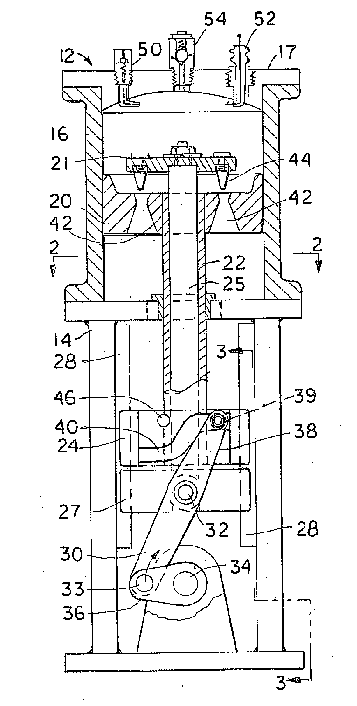
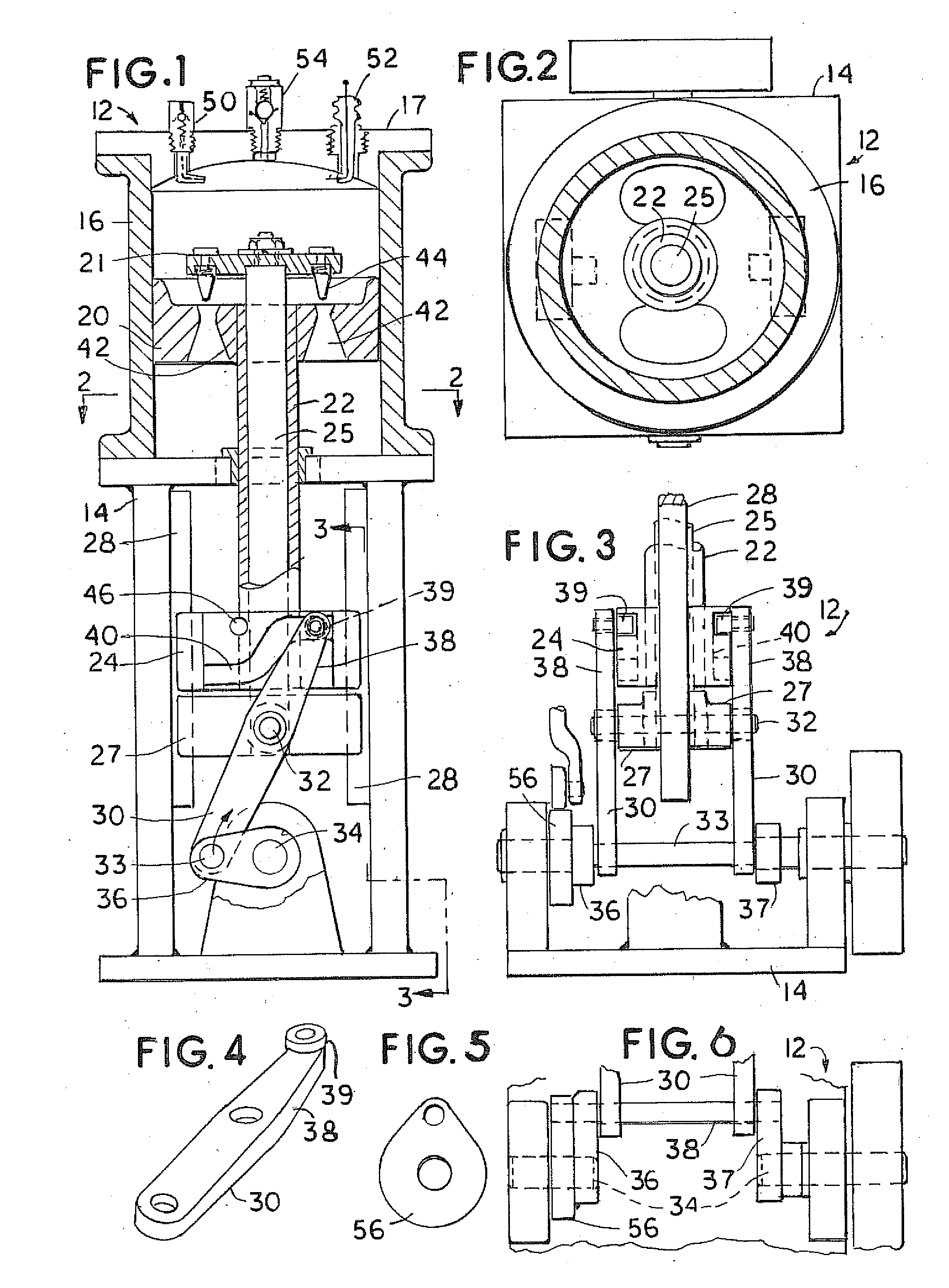
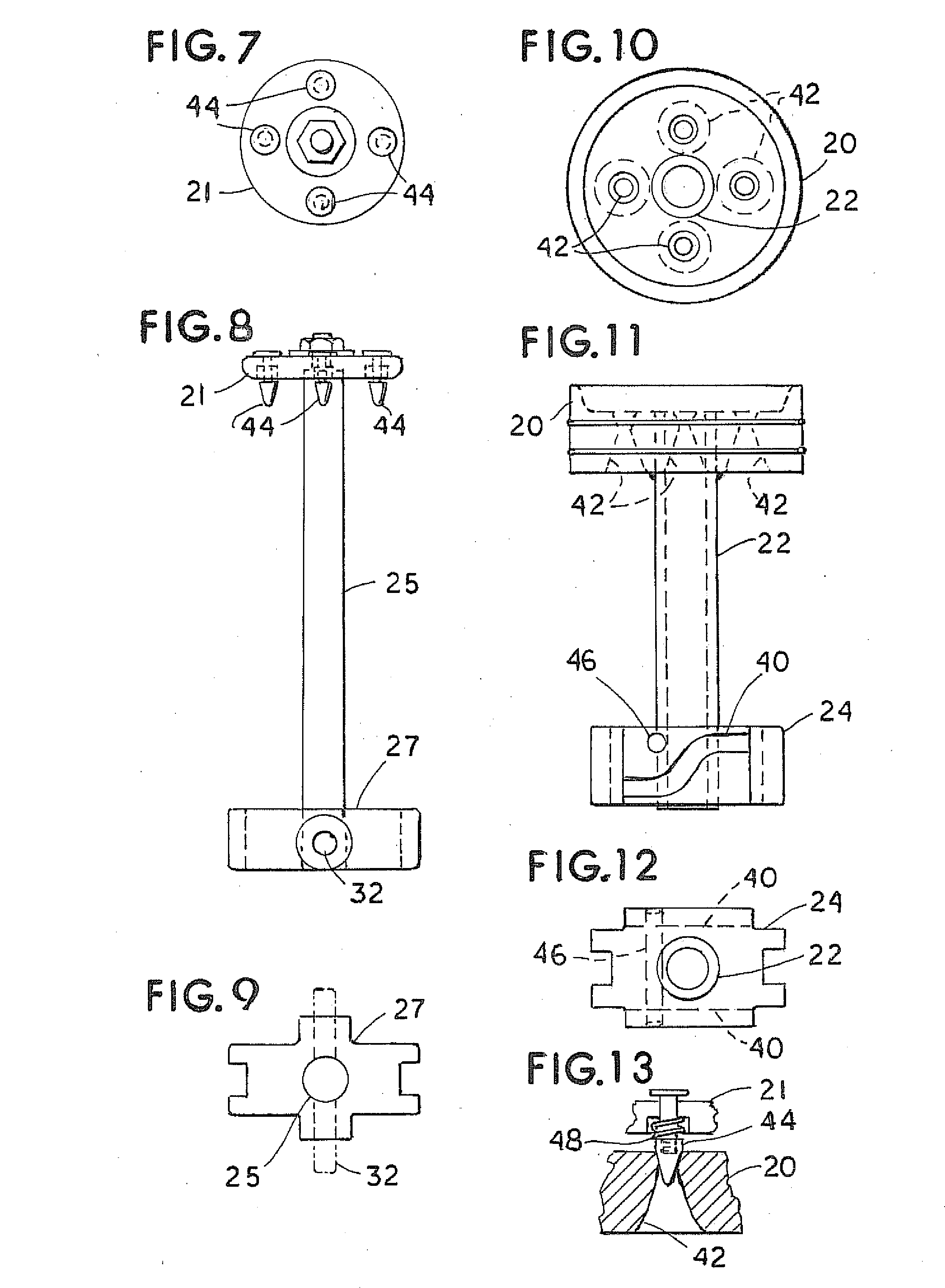
[0038]Referring to the drawings and in particular to FIGS. 1-18, engine 12 has a block or frame 14 with one or more cylinders 16. Each cylinder 16 has cap 17 a jet piston 20, and a piston lid 21 fitting over the jet piston. The jet piston is secured on a central tube 22 extending down to a crosshead 24. Piston lid 21 has a central rod 25 extending slip fit through tube 22 to a crosshead 27. Crossheads 24 and 27 have end slots to slide along guides 2P to hold the jet piston and 1d in alignment. Crosshead 27 can be omitted since rod 25 can be extended to hold pin 32.

[0039]A twin connecting rod 30 is connected on pin 32 to crosshead 27 and connected on pin 33 to crankshaft 34 between crank arms 36 and 37. Connecting rod 30 has twin cam arms 38 each extending up past crosshead 27 and along front and back faces of crosshead 24 each holding a cam roller 39 in a recessed cam track 40 on opposite faces of crosshead 24. Arms 38 swing cam rollers 39 from side to side along cam track 40 as the...


PUM


Abstract

This invention is a piston in cylinder engine using water injection into a relative vacuum heated to steam by expanding in the cylinder and by an electric arc or other heat source. The resulting steam explosion applies a work force on the piston. The piston has jet nozzles uncovered at the end of its work stroke to jet the piston to help propel it during the return stroke and to form a vacuum in place of the usual compression stroke. The piston has a cover plate with tapered pins depending into jet nozzles through the piston to block the jet nozzles during the main work stroke.

Description

RELATED APPLICATIONS[0001]This application claims priority of U.S. Provisional Patent application Ser. No. 61 / 232,664 filed Aug. 10, 2009 which is incorporated herein by reference.[0002]This invention is a reciprocating piston two-stroke engineFIELD AND BACKGROUND OF THE INVENTION[0003]Unlike present engines it uses exhaust gas to propel during the return stroke of the piston. It is especially designed to make steam at a low pressure or vacuum in the head end of a cylinder from hot water or steam injection. Preferably an electric arc adds heat in the cylinder to keep steam under increased pressure for the work stroke. It has jet nozzles in the piston opened at the end of the work stroke to help propel the exhaust stroke and exhaust the cylinder during the return stroke to a low pressure before the next cycle where it would first draw a vacuum and take on a small charge of water that turns to steam.[0004]Internal combustion engines now compress an sir fuel mix which is ignited in the...

Claims


Application Information

Patent Timeline
IPC IPC(8): F02F3/00
CPCF01K21/02F04B9/047F03C1/0406
Inventor BARRY, LEONARD D.
Owner BARRY LEONARD D
Why Eureka
Try Eureka