Mechanisms for detecting tampering of an electronic device

a technology for electronic devices and detecting tampering, which is applied in the direction of casings/cabinets/drawers, instruments, casings/cabinets/drawers details of electric devices, etc., can solve the problems of electronic devices such as desktop personal computers, laptops or notebook computers, smartphones, and consumer abuse, and achieve the effect of detecting consumer abuse and exposing electronic devices to liquids

Active Publication Date: 2011-02-10
APPLE INC
View PDF22 Cites 67 Cited by
  • Summary
  • Abstract
  • Description
  • Claims
  • Application Information

AI Technical Summary

Benefits of technology

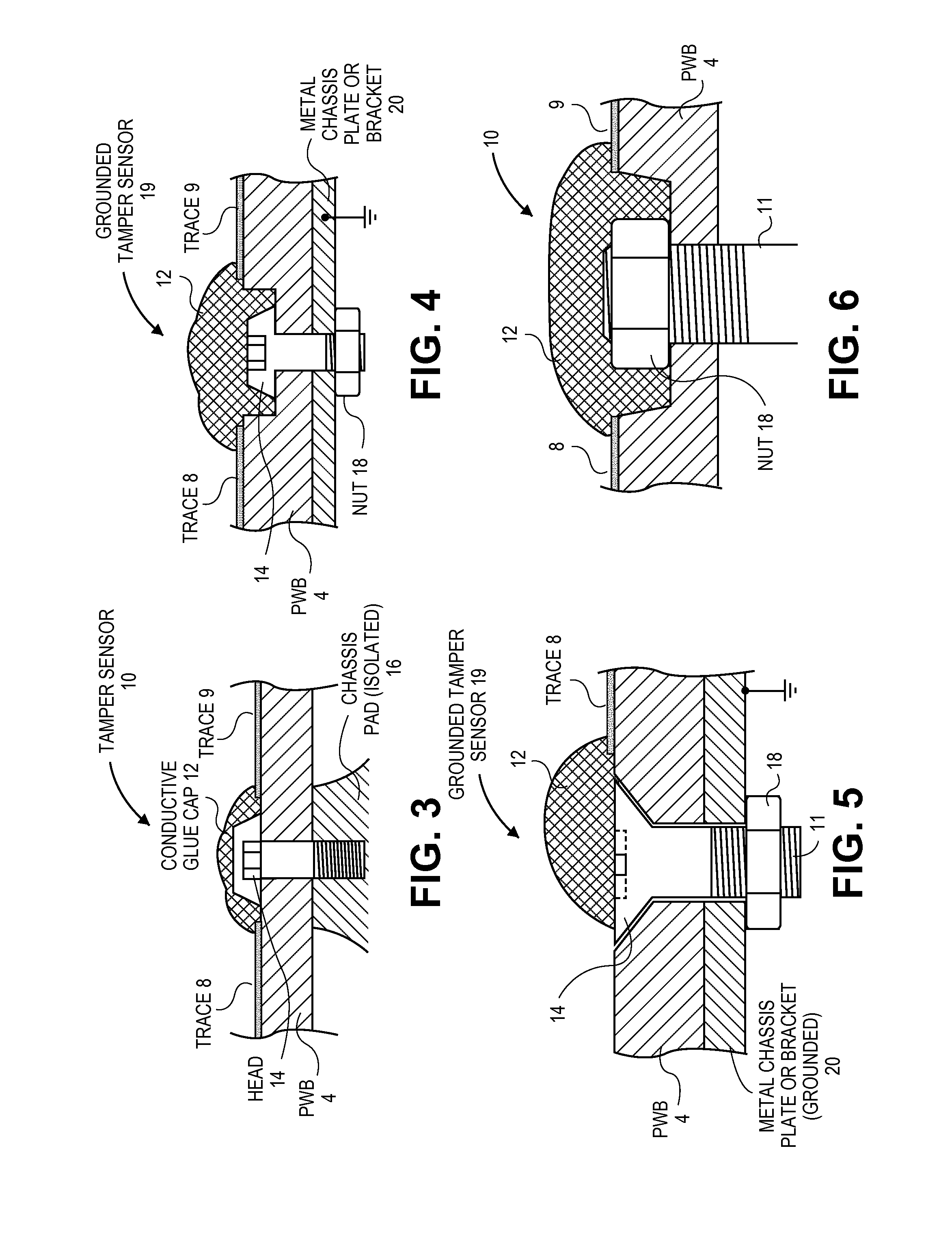
[0014]Where more than one tamper sensor is desired (e.g., when multiple fasteners are needed to secure the PWB to the chassis), the pairs of circuit traces associated with each hole may be connected to each other in series. The sensing circuit is then coupled to detect any change in the impedance of the entire conductive path that runs through all of the series-connected tamper sensors. Thus, with each tamper sensor being “normally shorted” (or exhibiting “continuity”) in its untampered state, tampering with any one of the sensors results in an “open” circuit that is detected by the sensing circuitry as a threshold change in impedance.
[0015]In some cases, the electronic device may be relatively large or complex with a multi piece PWB or simply with a PWB that has a rela...

Problems solved by technology

In general, such warranty and return policies are intended only to cover failures and defects relating to the manufacture or design of the product, and typically do not cover product failure that occurs as the result of consumer abuse.
In fact, many warranty policies explicitly exclude returns or repair when damage from consumer abuse, whether intentional or unintentional, is the underlying cause of the product failure.
For example, consumer abuse may include exposing an electronic device to liquids, extreme temperatures, or excessive shock (e.g., the resulting impact from dropping the device).
Consumer abuse may also result from tampering which may include any interaction with the device that is not related to operating the device in a normal manner (e.g., opening the casing or housing of a device and adding, removing, or altering the internal components).
Electronic devices such as desktop personal computers, laptop or notebook comp...

Method used


Image

  • Mechanisms for detecting tampering of an electronic device
  • Mechanisms for detecting tampering of an electronic device
  • Mechanisms for detecting tampering of an electronic device

Examples


Embodiment Construction

[0030]Several embodiments of the invention with reference to the appended drawings are now explained. Whenever the shapes, relative positions and other aspects of the parts described in the embodiments are not clearly defined, the scope of the invention is not limited only to the parts shown, which are meant merely for the purpose of illustration. Also, while numerous details are set forth, it is understood that some embodiments of the invention may be practiced without these details. In other instances, well-known circuits, structures, and techniques have not been shown in detail so as not to obscure the understanding of this description.

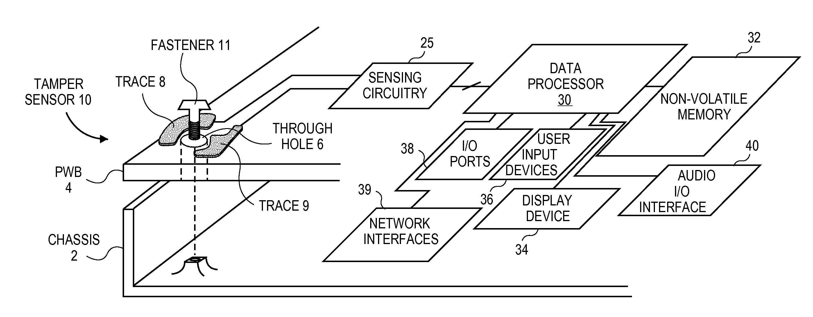
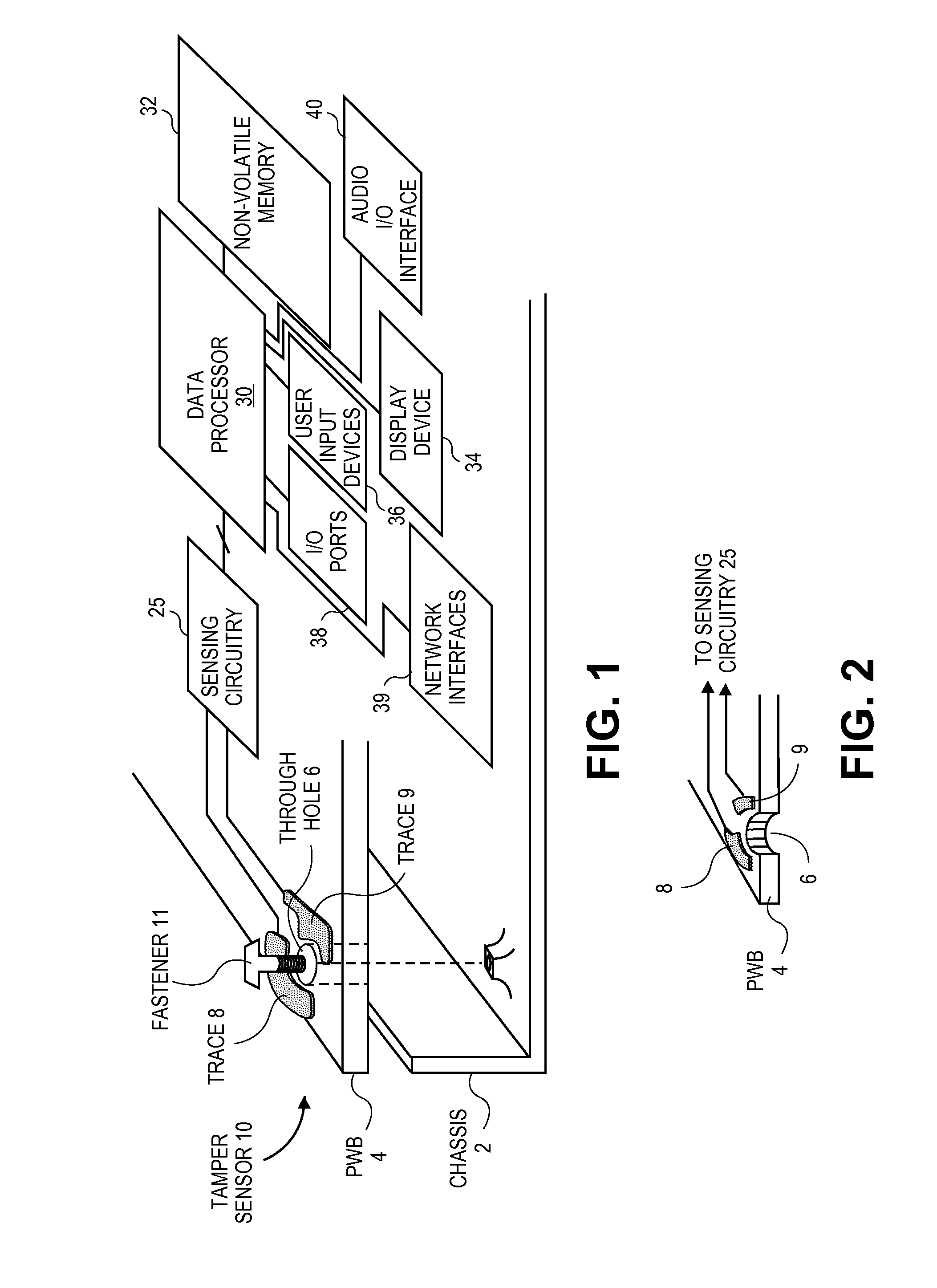
[0031]FIG. 1 is a perspective or elevation view of the inside of the housing of an electronic device, showing an opened chassis with a tamper sensor mechanism in accordance with an embodiment of the invention. The electronic device may be a desktop computer, a notebook / laptop computer, a personal digital assistant, a tablet computer, a smart phone,...


PUM


Abstract

An electronic device has a chassis, and a printed wiring board (PWB) having a hole. A fastener is installed in the hole thereby securing the PWB to the chassis. A pair of conductive traces is formed in the PWB. A cap, being an amount of conductive glue, covers a part of the fastener and fills an electrically insulating gap between the two traces, to thereby form a conductive path that connects the two traces. A sensing circuit is coupled to the traces, to detect a change in impedance of the path and signal a tamper event alert. Other embodiments are also described and claimed.

Description

RELATED APPLICATIONS[0001]This application claims the benefit of the earlier filing date of U.S. provisional application No. 61 / 232,686 filed Aug. 10, 2009, entitled “Mechanisms for Detecting Tampering With a Printed Circuit Board and Exposure to Water in an Electronic Device”.BACKGROUND[0002]1. Field[0003]The present invention relates generally to electronic devices and, more particularly, to techniques for detecting the occurrence of consumer abuse in electronic devices.[0004]2. Related Art[0005]This section is intended to introduce the reader to various aspects of art that may be related to various aspects of the present invention, which are described and / or claimed below. This discussion is believed to be helpful in providing the reader with background information to facilitate a better understanding of the various aspects of the present invention. Accordingly, it should be understood that these statements are to be read in this light, and not as admissions of prior art.[0006]El...

Claims


Application Information

Patent Timeline
IPC IPC(8): G01R27/26
CPCG06F21/86G08B13/128G08B13/1418G08B13/1445H05K1/0215H05K1/0268G01R1/10H05K1/0293H05K5/0208H05K7/1417H05K2201/10151H05K2201/10409H05K1/0275H05K5/02H05K7/14G08B13/14
Inventor JOHNSON, TIMOTHY M.
Owner APPLE INC
Why Eureka
Try Eureka