Separator for fuel cell

a fuel cell and separator technology, applied in the direction of collector/separator, fuel cell, cell components, etc., can solve the problems of gasket loosening, local deformation easily occurring in this region, and deterioration of the airtight performance of the gasket, so as to prevent local deformation of the separator

Active Publication Date: 2011-02-10
HYUNDAI MOTOR CO LTD +1
View PDF2 Cites 23 Cited by
  • Summary
  • Abstract
  • Description
  • Claims
  • Application Information

AI Technical Summary

Benefits of technology

[0021]The present invention preferably provides a separator for a fuel cell, in which a strength reinforcing means is integrally formed in a region, which is not suitably supported by a gasket, for example, preferably, in a flow diffusion region of the separator, in which any suitable support means is not provided, over the region from manifolds, through which reactant gases and coolant are suitably supplied, to a reaction flow field, in which a reaction takes place, thus suitably preventing local deformation of the separator.
[0022]In a preferred embodiment, the present invention provides a separator for a fuel cell, in which a reactant gas and coolant entrance region is suitably provided at each of both ends, a reaction flow field region is suitably provided between the reactant gas and coolant entrance regions, and a flow diffusion region is suitably disposed between the reactant gas and coolant entrance region and the reaction flow field region, the separator preferably including, but not only limited to, a strength reinforcing means integrally formed in the flow diffusion region to suitably prevent local deformation of the separator.

Problems solved by technology

Therefore, local deformation easily occurs in this region by a pressure difference between the reactant gases and the coolant during operation of the fuel cell.
Therefore, there are problems in that local deformation may occur due to the pressure difference between the reactant gases and the coolant during operation of the fuel cell to suitably reduce the surface pressure of the adjacent gasket, which causes the gasket to get loose, thus suitably deteriorating the airtight performance of the gasket.

Method used


Image

  • Separator for fuel cell
  • Separator for fuel cell
  • Separator for fuel cell

Examples


Embodiment Construction

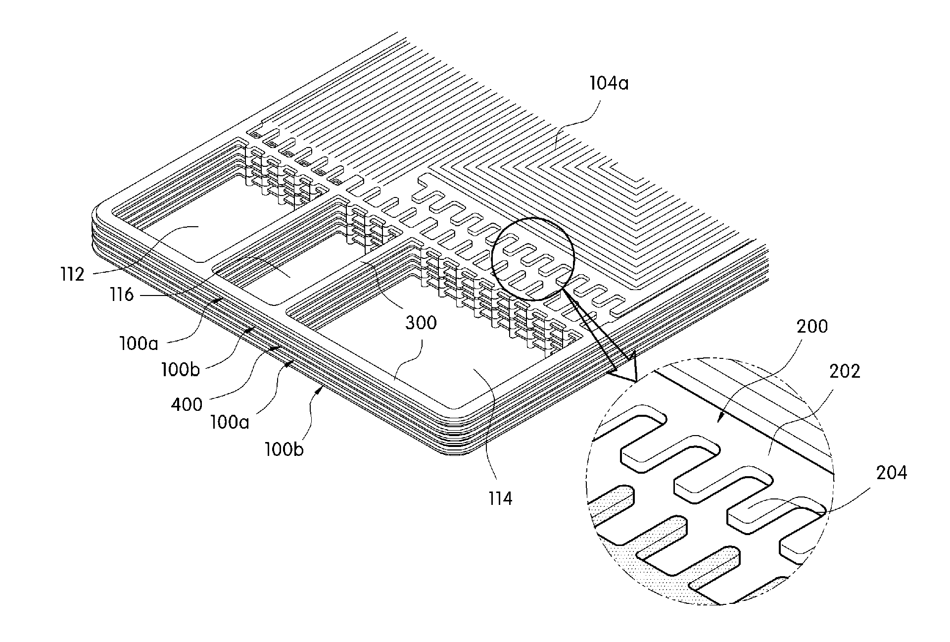
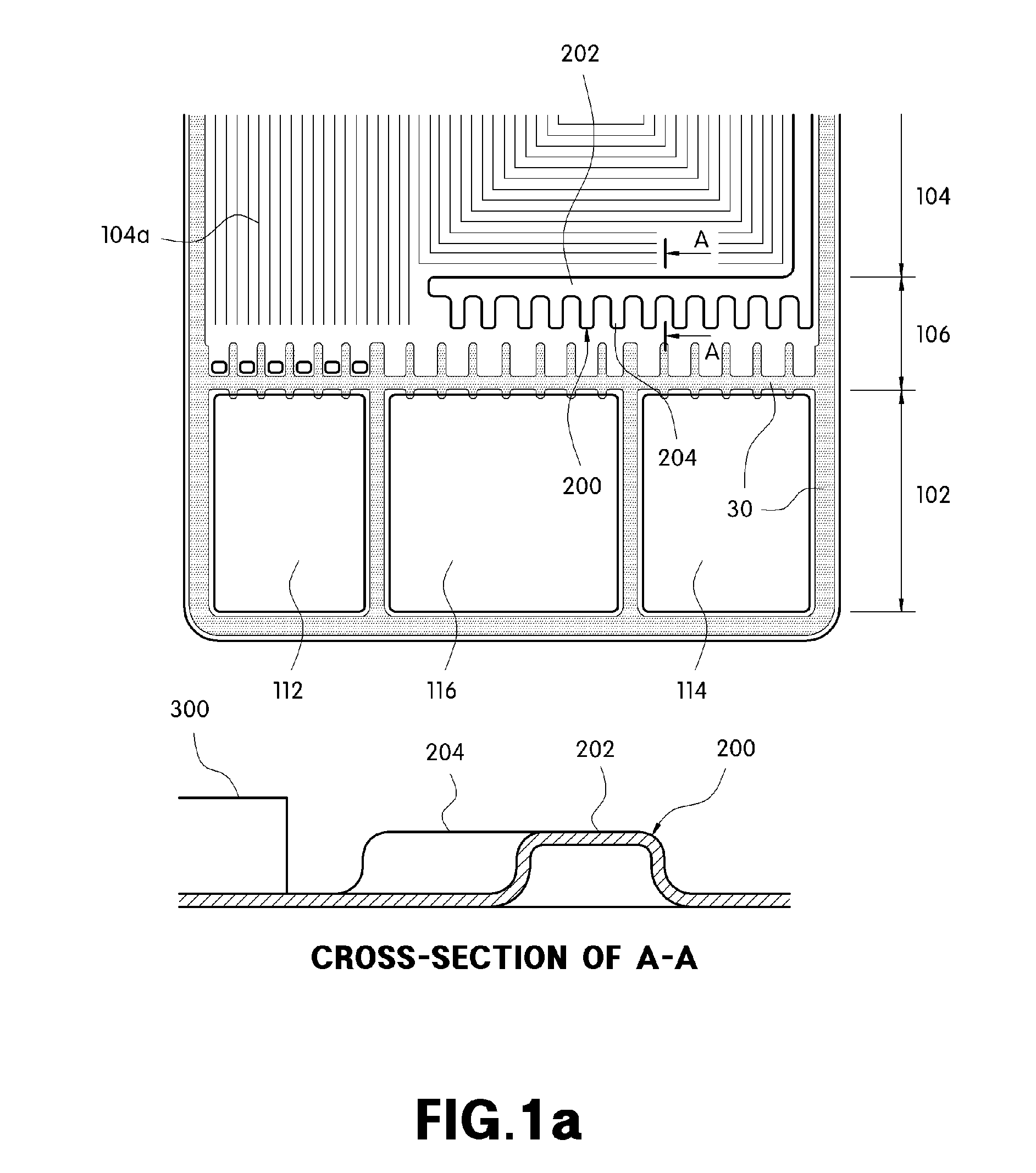
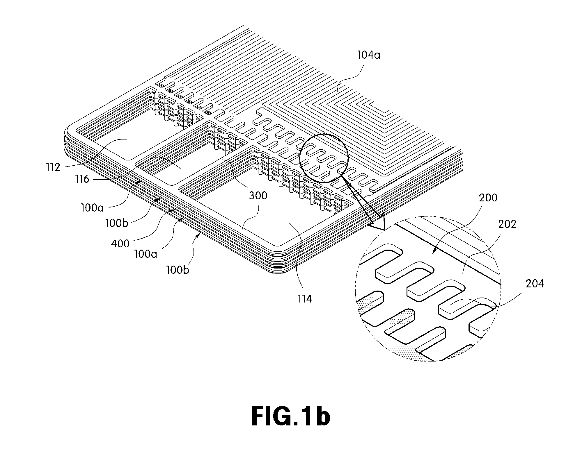
[0039]The present invention, in a first aspect, features a separator for a fuel cell, in which a reactant gas and coolant entrance region is provided at each of both ends, a reaction flow field region is provided between the reactant gas and coolant entrance regions, and a flow diffusion region is disposed between the reactant gas and coolant entrance region and the reaction flow field region.

[0040]In one embodiment, the separator comprises a strength reinforcing means.

[0041]In another embodiment, the strength reinforcing means is integrally formed in the flow diffusion region to prevent local deformation of the separator.

[0042]In another further embodiment, the strength reinforcing means is integrally formed in the flow diffusion region by work-hardening.

[0043]In still another further embodiment, the strength reinforcing means further comprises a main rib arranged in the width direction of the flow diffusion region and a plurality of sub-ribs extending from the main rib adjacent to...


PUM

PropertyMeasurementUnit
thicknessaaaaaaaaaa
strengthaaaaaaaaaa
widthaaaaaaaaaa

Abstract

The present invention preferably provides a separator for a fuel cell, in which a strength reinforcing means is integrally formed in a region, which is not supported by a gasket, over the region from manifolds, through which reactant gases and coolant are supplied, to a reaction flow field, in which a reaction takes place, thus suitably preventing local deformation of the separator.

Description

CROSS-REFERENCE TO RELATED APPLICATION[0001]This application claims under 35 U.S.C. §119(a) the benefit of Korean Patent Application No. 10-2009-0071681 filed Aug. 4, 2009, the entire contents of which are incorporated herein by reference.BACKGROUND[0002](a) Technical Field[0003]The present disclosure relates, in general, to a separator for a fuel cell. More particularly, in preferred embodiments, the present invention relates to a separator for a fuel cell, in which a strength reinforcing means is integrally formed in a region, and further is not supported by a gasket, over the region from manifolds, through which reactant gases and coolant are suitably supplied, to a reaction flow field, in which a reaction takes place, thus suitably preventing local deformation of the separator.[0004](b) Background Art[0005]A typical structure of a fuel cell stack will be described briefly with respect to exemplary FIG. 8. Preferably, a membrane electrode assembly (MEA) is located in the middle o...

Claims


Application Information

Patent Timeline
Patent Type & Authority Applications(United States)
IPC IPC(8): H01M2/02
CPCH01M8/0206H01M8/0247Y02E60/50H01M8/0273H01M2008/1095H01M8/0263H01M8/02
Inventor CHIN, SANG MUNKIM, SAE HOONYANG, YOO CHANGYIM, CHUL HOBAECK, SUK MINHEO, SEONG IL
Owner HYUNDAI MOTOR CO LTD
Why Eureka
Try Eureka