
Circuit Arrangement and Method for Starting a Discharge Lamp

Inactive Publication Date: 2011-02-17
OSRAM GMBH
View PDF4 Cites 0 Cited by
  • Summary
  • Abstract
  • Description
  • Claims
  • Application Information

AI Technical Summary

Benefits of technology

[0009]The fact that the switch is in the form of a threshold value switch opens up the possibility of using a large number of possible physical switches; for example the first switch can be a spark gap or a SIDAC or a component with a similar threshold value characteristic. A spark gap as the threshold value switch provides the advantage of a very low internal resistance and the high starting efficiency associated therewith. The threshold value switch in this case preferably has a parallel capacitance, via which a voltage across the threshold value switch can be built up by means of a transfer of charge to the capacitance.

Problems solved by technology

However, spark gaps have the disadvantage that the breakdown voltage is severely subject to tolerances, and the starting energy found in the primary circuit as a result of the charging of the starting capacitor C1 thus likewise fluctuates to a considerable extent.
This makes the process of starting th

Method used


Image

  • Circuit Arrangement and Method for Starting a Discharge Lamp
  • Circuit Arrangement and Method for Starting a Discharge Lamp
  • Circuit Arrangement and Method for Starting a Discharge Lamp

Examples


Example

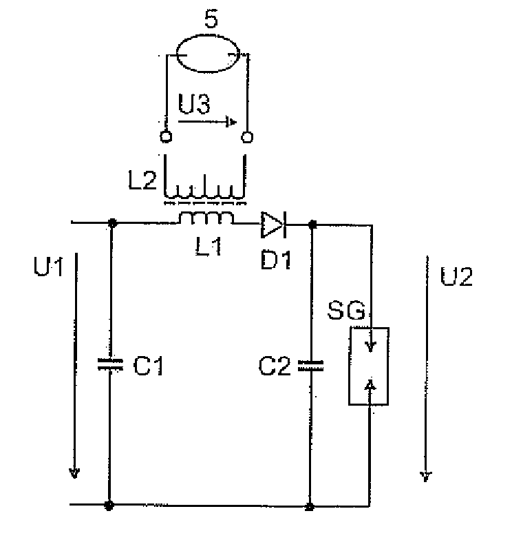
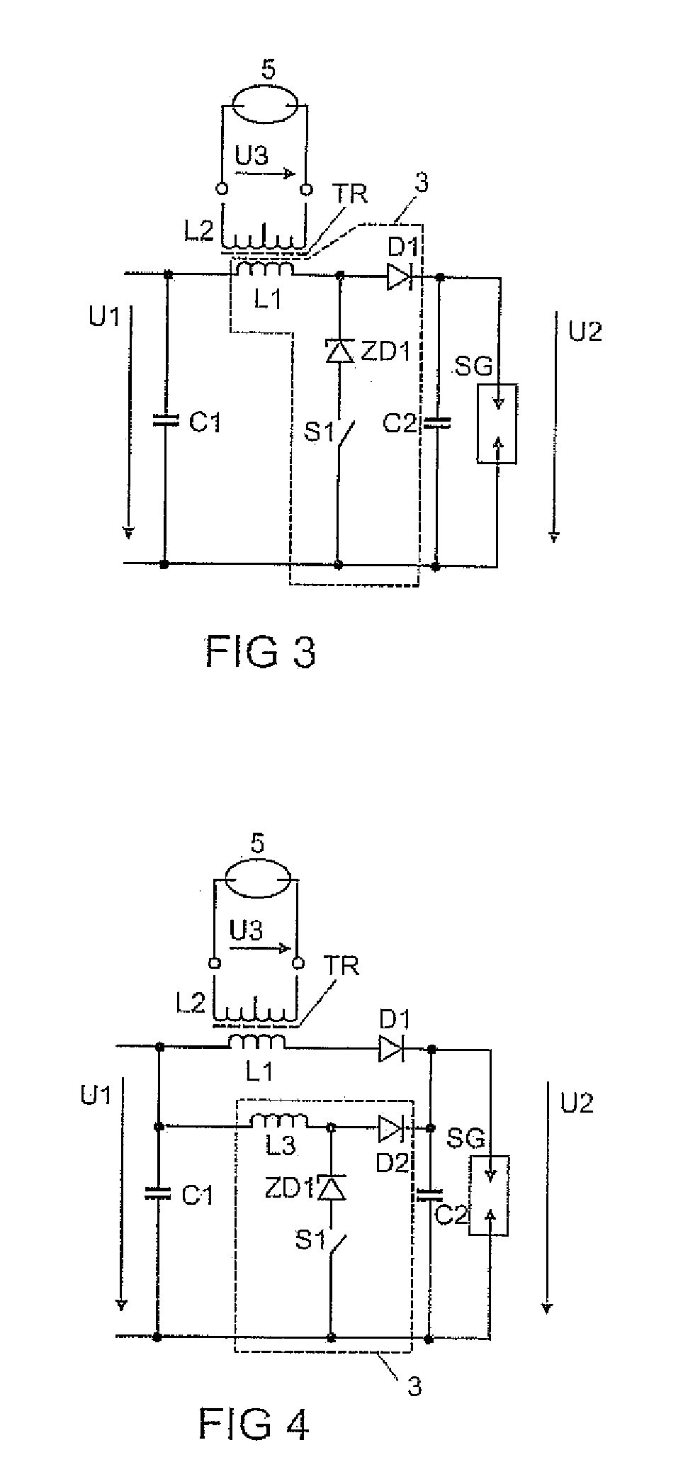
[0026]The component values of a preferred configuration of the third embodiment are given in the table below:

C168 nFC20 . . . 5 nFL11.3 μHL2700 μHLDNot providedU1200 V . . . 700 VD1Diode with 600 V off-state voltageD2Diode with 600 V off-state voltageZD1zener diode with 400 V zener voltageL3 470 μHSGSpark gap with 800 V ± 20% breakdown voltage

[0027]In this case, the voltage U1 can be varied from 200V to 700V depending on the desired starting energy. In this case, the starting energy can depend on the lamp state of the gas discharge lamp 5, for example it may be higher in the case of a hot lamp. At a voltage U1 of 500V the starting energy is, for example, 0.5*70 nF*(500V)2=8.75 mJ corresponding to a starting pulse level of 17 kV. At a voltage U1 of 700V, the starting energy is, for example, 0.5*70 nF*(700V)2=17.15 mJ, corresponding to a starting pulse level of 22 kV. The switch-on time of the switch / switching transistor S1 is in this case varied corresponding to the voltage U1 in suc...

Example

[0029]The component values of a preferred configuration of the fourth embodiment will be given in the table below:

C168 nFC20.5 . . . 5 nFL11.3 μHLD 1 . . . 5 μHL2 700 μHU1500 . . . 600 VZD1zener diode with 400 V zener voltageSGSpark gap with 800 V ± 20% breakdown voltage

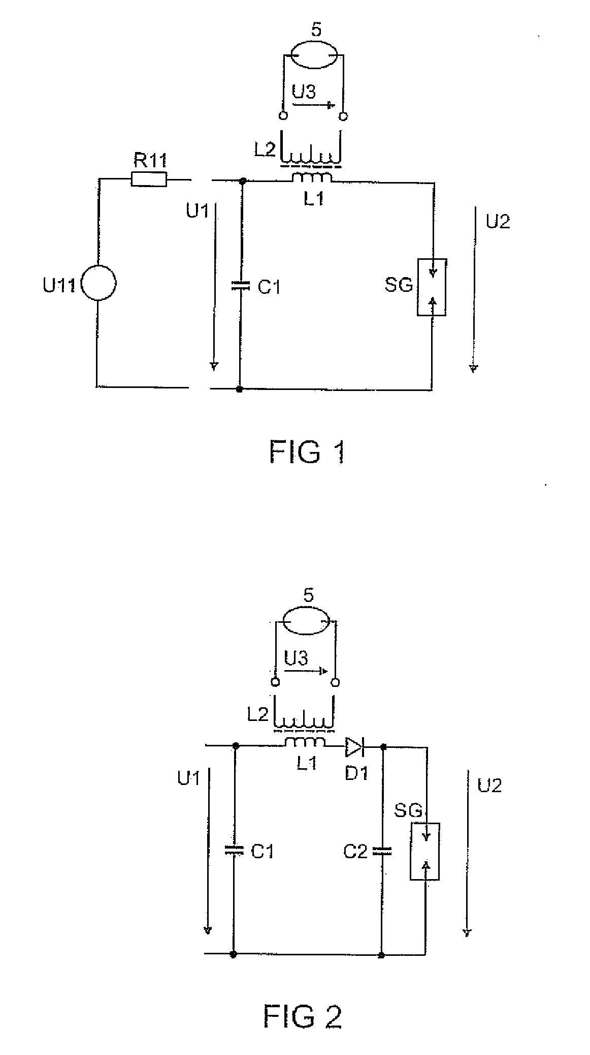
[0030]This switching mechanism with a very fast-response threshold value switch or a fast-response spark gap SG can naturally also be applied in accordance with the invention to a circuit arrangement known per se, as in FIG. 1. If in this case a voltage is applied to the spark gap SG from an external voltage source (not shown here) and the spark gap SG switches quickly, the voltage U1 applied to the starting capacitor C1 can be decoupled from the voltage U2 triggering the threshold value switch or the spark gap SG by means of L1 without the additional components being required. This represents the simplest embodiment for a starting method according to the invention and only requires one first threshold value switch w...


PUM


Abstract

A circuit arrangement for starting a discharge lamp, with a primary circuit, which comprises a series circuit comprising an inductance (L), a starting capacitor (C1) and a first switch (SG), the switch being in the form of a threshold value switch, and the inductance comprising the primary winding (L1) of the starting transformer (TR), and the primary circuit being designed to generate a starting pulse for the discharge lamp at the secondary winding (L2) of a starting transformer (TR), the primary circuit having two decoupled voltages, a first voltage, which is correlated substantially with the energy of the starting pulse, and a second voltage, which controls the operating time of the switch, the first voltage being lower than the threshold value of the first switch. Also disclosed is a method for starting a discharge lamp, with a primary circuit which generates a starting pulse for the discharge lamp at the secondary winding of a starting transformer, the primary circuit comprising a series circuit comprising an inductance, a starting capacitor and a first switch, which is in the form of a threshold value switch, characterized by the following steps: charging the starting capacitor to a first voltage, and applying a second voltage to the first switch in order to switch on said switch.

Description

RELATED APPLICATIONS[0001]This application claims the priority of German patent application no. 10 2009 032 985.4 filed Jul. 14, 2009.FIELD OF THE INVENTION[0002]The invention relates to a circuit arrangement for starting a discharge lamp, with a primary circuit, which comprises a series circuit comprising an inductance, a starting capacitor and a first switch, the switch being in the form of a threshold value switch, and the inductance comprising the primary winding of the starting transformer, and the primary circuit being designed to generate a starting pulse for the discharge lamp at the secondary winding of a starting transformer.BACKGROUND OF THE INVENTION[0003]The invention is based on a circuit arrangement for starting a discharge lamp in accordance with the generic type of the main claim.[0004]FIG. 1 shows a circuit arrangement for starting a discharge lamp in accordance with the prior art, in which a high circuit current through a primary winding L1 of a starting transform...

Claims


Application Information

Patent Timeline
IPC IPC(8): H05B41/36
CPCH05B41/2881H05B41/04
Inventor MUEHLSCHLEGEL, JOACHIM
Owner OSRAM GMBH
Learn More