
Liquid lead storage battery and battery system

Active Publication Date: 2013-12-05
GS YUASA INT LTD
View PDF6 Cites 2 Cited by
  • Summary
  • Abstract
  • Description
  • Claims
  • Application Information

AI Technical Summary

Benefits of technology

The patent aims to improve the life of a special type of battery used in portable electronic devices. The invention does this by stopping the negative material in the battery from releasing carbon.

Problems solved by technology

Negative electrode sulfation is a phenomenon in which a negative active material is changed into lead sulfate which is bulky and difficult to be reduced to metal lead, so that a storage battery loses its capacity.
In the sealed lead storage battery, an electrolyte solution is retained in a retainer mat, and therefore has low fluidity.
Also, since a difference in specific gravity between carbon and the electrolyte solution is relatively small, carbon is blown up by convection of the electrolyte solution and a generated gas, and deposited on the upper part of an element, so that a short circuit may be caused in the worst case.
Therefore, in the liquid lead storage battery, it is difficult to include 0.3% by mass or more of carbon in the negative active material.

Method used


Image

  • Liquid lead storage battery and battery system
  • Liquid lead storage battery and battery system
  • Liquid lead storage battery and battery system

Examples


example

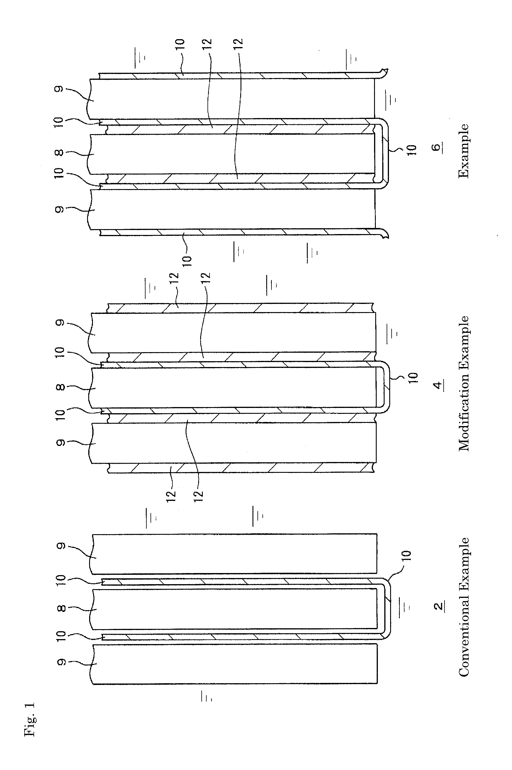
[0023]FIG. 1 shows vertical sectional views of principal constitutional parts of liquid lead storage batteries in Example, Modification Example and Conventional Example, and Tables 1 and 2 show the performance of the liquid lead storage batteries. In FIG. 1, reference numerals 2, 4 and 6 denote principal constitutional parts of liquid lead storage batteries of Conventional Example, Modification Example and Example, respectively. Reference numeral 8 denotes a negative electrode plate, and reference numeral 9 denotes a positive electrode plate. The negative electrode includes an active material containing spongy lead and the positive electrode includes an active material containing lead dioxide with each electrode further including a general grid formed of a lead-calcium-tin-based or lead-calcium-based alloy. A method for production of each grid is arbitrary. The negative active material includes carbon; lignin, synthetic resin fibers, barium sulfate or the like; and a lead powder. Th...

second modification example

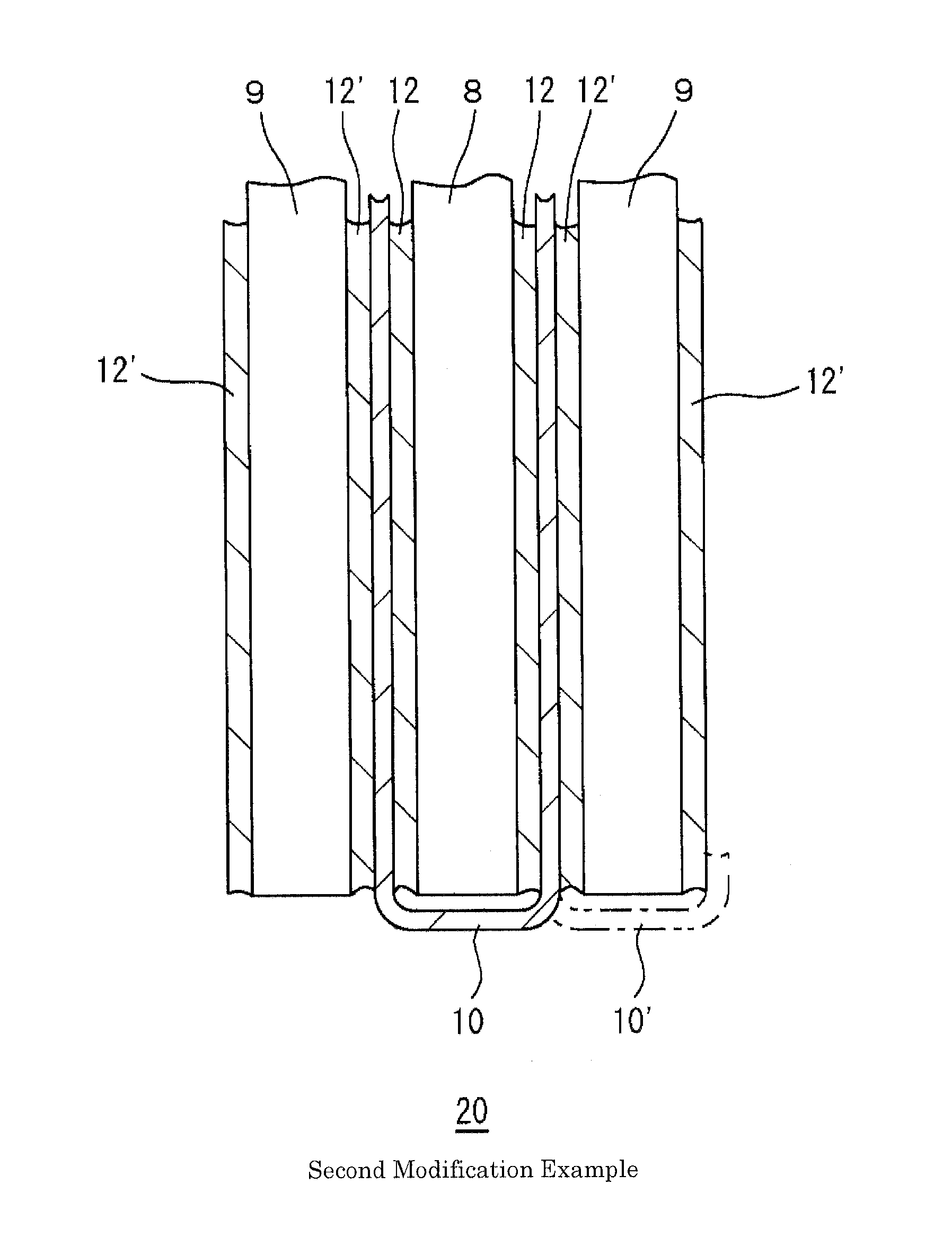
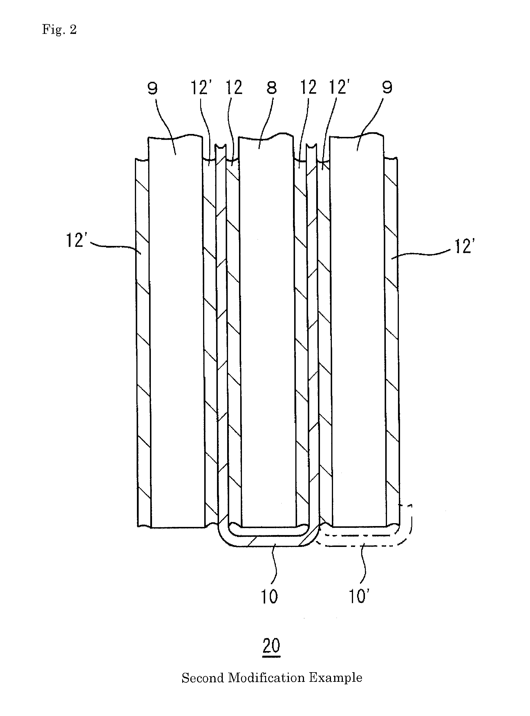
[0035]A principal constitutional part 20 of a liquid lead storage battery in second Modification Example is shown in FIG. 2, where the symbols identical to those in FIG. 1 denote the same components. An elastic sheet 12′ is also added between a microporous separator 10 and a positive electrode plate 9 with respect to optimum Example in FIG. 1. The additional elastic sheet 12′ abuts on the positive electrode plate 9 to prevent a positive active material from falling off the positive electrode plate 9. The additional elastic sheet 12′ prevents degradation of the microporous separator 10 by preventing deposits from the positive active material from coming into contact with the microporous separator 10 during charge-discharge. The microporous separator 10 may be changed as shown by a chain line 10′ in the figure to store the positive electrode plate 9 instead of storing the negative electrode plate 8.

Battery System

[0036]A battery system of Example is shown in FIG. 3, where each arrow sh...


PUM


Abstract

A liquid lead storage battery includes a negative electrode plate, a positive electrode plate and an electrolyte solution. The both plates are arranged so as to face each other in a thickness direction and immersed in the electrolyte solution. The negative electrode plate includes an active material containing carbon. An elastic sheet formed of a porous material is arranged between the negative electrode plate and the positive electrode plate so as to press the negative electrode plate from both sides in the thickness direction.

Description

TECHNICAL FIELD[0001]The present invention relates to a liquid lead storage battery and a battery system using the same.BACKGROUND ART[0002]With introduction of idling stop cars or the like, liquid lead storage batteries have been increasingly used in a partially charged state (Partial State of Charge; PSOC). For use in PSOC, the liquid lead storage battery often ends its life due to sulfation of a negative electrode. Negative electrode sulfation is a phenomenon in which a negative active material is changed into lead sulfate which is bulky and difficult to be reduced to metal lead, so that a storage battery loses its capacity. It is known to be effective to add fine and electrically conductive carbon such as carbon black to a negative active material in a large amount for suppressing negative electrode sulfation (Patent Document 1; JP 3185508 B). For example, Patent Document 1 discloses that negative electrode sulfation can be suppressed by including 0.4 to 7.5% by mass of carbon i...

Claims


Application Information

Patent Timeline
IPC IPC(8): H01M10/12H01M2/18H01M4/583B60R16/03H01M50/409H01M50/463H01M50/489H01M50/491
CPCH01M10/12B60R16/03H01M2/18H01M4/583H01M4/14H01M10/06Y02E60/10H01M50/409H01M50/463Y02P70/50H01M50/491H01M50/489
Inventor FUJIWARA, YOSHIOMI
Owner GS YUASA INT LTD
Learn More