
Illumination device as well as observation device

a technology of observation device and irradiation device, which is applied in the field of irradiation device, can solve the problems of poor contrast of phase objects, red reflexes not appearing uniformly bright over the pupil of patients,

Active Publication Date: 2011-02-17
CARL ZEISS MEDITEC AG
View PDF4 Cites 5 Cited by
  • Summary
  • Abstract
  • Description
  • Claims
  • Application Information

AI Technical Summary

Benefits of technology

[0021]According to the invention, this object is solved by the illumination device with the features according to the independent patent claims 1, 7 and 9, the observation device with the features according to independent patent claims 27, 28 and 29 as well as the special uses according to independent patent claims 34 and 35. Other advantages, features, details, aspects and effects of the invention result from the subclaims, the description, as well as the drawings. Features and details that are described in connection with the illumination device according to the invention, thus also apply, obviously, in connection with the observation device according to the invention and vice versa. The same is true for the particular uses.
[0022]According to the first aspect of the invention, an illumination device is provided for one, two or more—particularly stereoscopic—observation beam paths, with an observation device having an observation light bundle for each path, having at least one light source for producing at least one illumination light bundle for illuminating an object to be observed, in particular, an eye to be observed, wherein at least two partial illumination light bundles are provided and wherein each partial lighting illumination bundle runs coaxially to a corresponding observation light bundle. The illumination device is hereby characterized according to the invention in that the partial illumination light bundles are / will be formed in such a way that they form two or more lighting spots that are variable in size on the fundus of an object to be observed, for example, an eye.
[0023]The essence of the present invention thus first lies in a new conception of the illumination device. The new conception of the illumination device, among other things, consists of the fact that the latter produces at least two light bundles originating from one or even several light sources, wherein the optical axes of these light bundles run coaxially to the optical axes of the observation light bundles.
[0024]For example, a single light source can be provided, which first produces a single illumination light bundle. This illumination light bundle is subsequently divided into the desired number of partial illumination light bundles by suitable means, for example, beam splitters or the like. For example, it may also be provided, however, that the illumination device has two or more light sources, wherein each light source then produces one partial illumination light bundle.
[0025]In this way, a true coaxial illumination is created. “Coaxial” is therefore generally an illumination near the axis. This includes both an illumination under precisely zero degree as well as an oblique illumination at a very small angle near the axis. This could be denoted as “substantially coaxial”. Examples of this are explained in more detail in the further course of the description.
[0026]The new illumination concept of at least two coaxial partial illumination light bundles, according to the invention, produces two or more lighting spots that are variable in size on the fundus of the object to be observed, for example, an eye.

Problems solved by technology

This has the consequence, however, that the “red reflex” does not appear uniformly bright over the patient's pupil.
Tests with coaxial illumination in fact led to a good, homogeneous “red reflex”, but to a poor contrasting of phase objects, and thus previously have not proven suitable in practice.

Method used


Image

  • Illumination device as well as observation device
  • Illumination device as well as observation device
  • Illumination device as well as observation device

Examples


Embodiment Construction

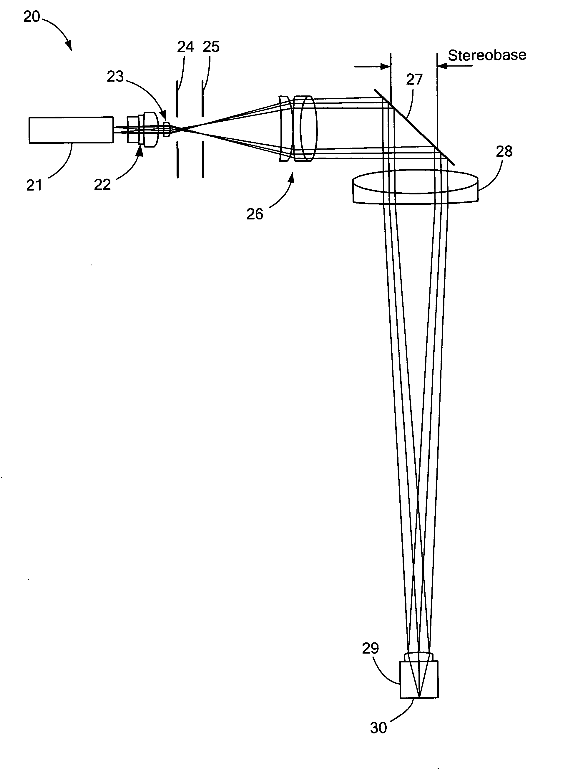
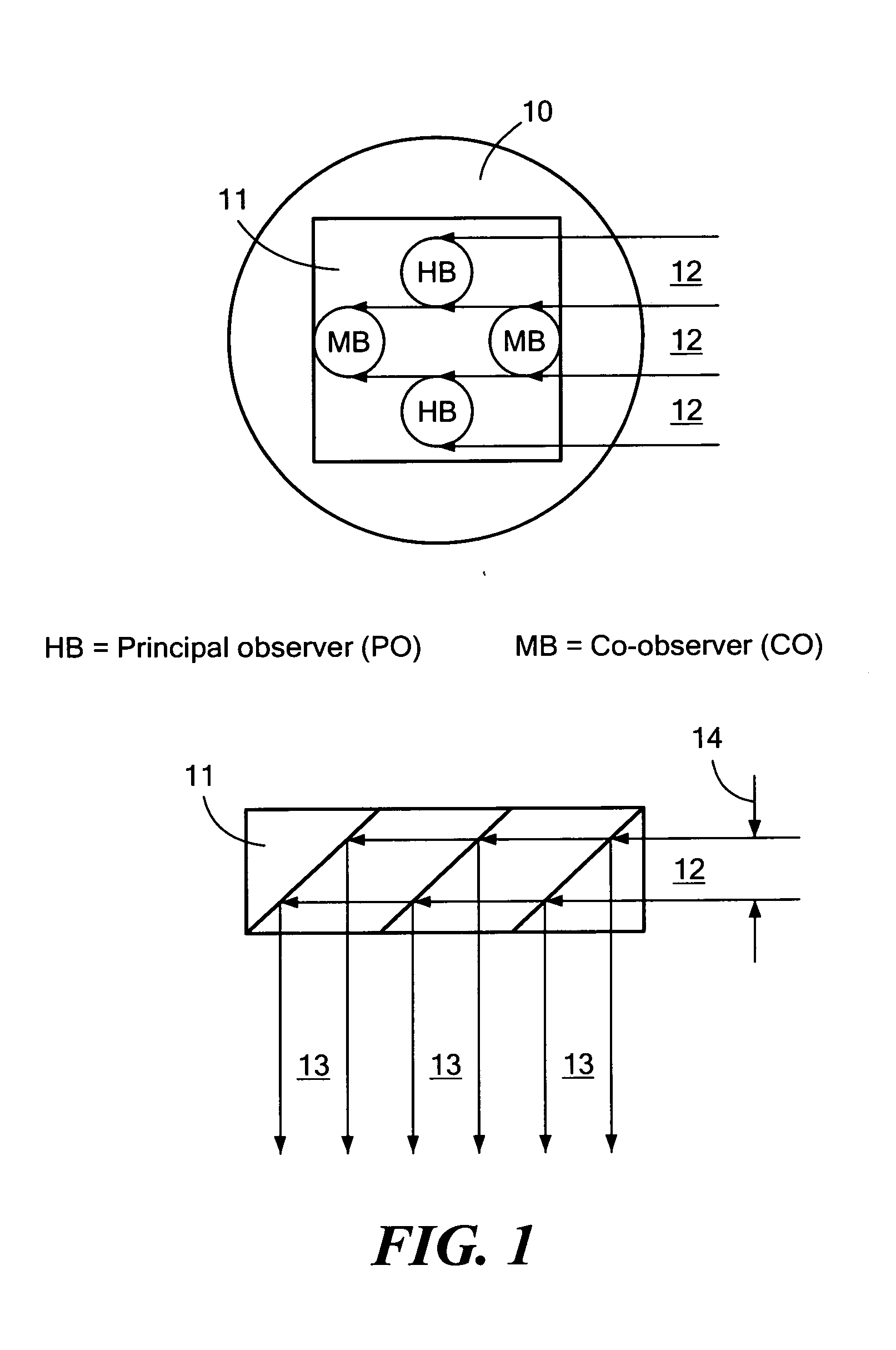
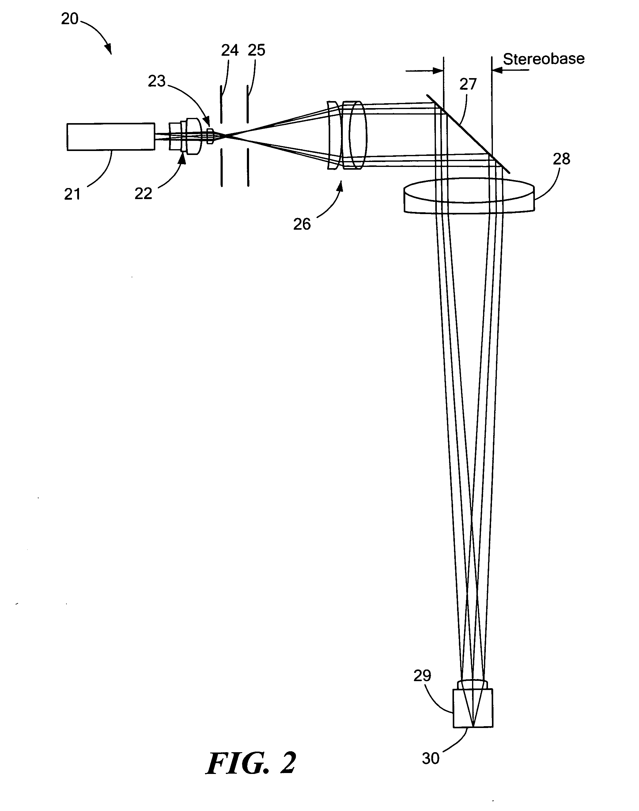
[0093]Parts of an illumination device, which is utilized in an observation device, are shown in FIG. 1. The observation device involves a stereo operating microscope for use in ophthalmic surgery, for example, for conducting cataract operations. A very uniform, bright “red reflex” is obtained by means of the illumination device by splitting the illumination light bundle 12 into several partial illumination light bundles 13. This is performed by means 11 for splitting the illumination light bundle, which may provide a suitable mirror / prism arrangement for this purpose. The partial illumination light bundles 13 are thus guided in such a way that the object to be observed, in the present case, a patient's eye, is illuminated from the same direction from which the observation is also produced (0° illumination), relative to the left and right observation beam paths of the operating microscope.

[0094]As can be taken from the left-hand side of the figure, observation beam paths both for a p...


PUM


Abstract

Disclosed are an illumination device for an observation device comprising one, two or more observation beam paths with one respective beam of observation rays, especially for an ophthalmologic surgical microscope, and a corresponding observation device. Said illumination device is provided with at least one light source for generating at least one beam of observation rays in order to illuminate an object that is to be observed. According to one embodiment of the invention, at least two partial bundles of illumination rays are provided, each of which extends coaxial to a corresponding beam of observation rays, while the partial beams of illumination rays are embodied so as to form two or several illumination spots on the fundus of an object that is to be observed, e.g. an eye, said illumination spots having variable sizes, thus allowing the illumination beam to cooperate in a precisely defined manner with the observation beam paths, which makes it possible to meet especially the practical requirements regarding homogeneity of the red reflex.

Description

CROSS-REFERENCE TO RELATED APPLICATIONS[0001]The present application is a divisional of U.S. patent application Ser. No. 11 / 659,594, inventors Peter Reimer et al., filed Feb. 6, 2007, the disclosure of which is incorporated herein by reference.BACKGROUND OF THE INVENTION[0002]The present invention relates first to an illumination device for an observation device according to the preamble of patent claims 1, 7 and 9. In addition, the invention relates to an observation device according to the preambles of patent claims 27, 28 and 29 as well as special uses according to the preambles of patent claims 34 and 35.[0003]For example, an observation device may involve an operating microscope. In particular, the observation device can be designed as an ophthalmologic operating microscope, which is utilized, for example, for a special application in eye surgery, i.e., cataract surgery.[0004]In the case of cataract surgery, a lens of the eye—which is clouded, for example, due to the cataract—i...

Claims


Application Information

Patent Timeline
IPC IPC(8): A61B3/12
CPCA61B3/13A61B19/52A61B3/1225A61B19/5223A61B3/12A61B19/5202A61B90/36A61B90/30A61B90/20
Inventor REIMER, PETERABRAMOWSKY, HEINZKOLSTER, DANIELSTRAEHLE, FRITZABELE, ALFONS
Owner CARL ZEISS MEDITEC AG
Learn More