Combined Coherent and Incoherent Imaging LADAR

a laser radar and coherent technology, applied in the field of long-range eye-safe laser radar (ladar) system, can solve the problems of lack of lack of ability to discern the object's micro-doppler vibration spectrum, and lack of design ability to develop simultaneous 3d image information

Active Publication Date: 2011-02-17
USA REPRESENTED BY THE SEC OF THE NAVY
View PDF6 Cites 20 Cited by
  • Summary
  • Abstract
  • Description
  • Claims
  • Application Information

AI Technical Summary

Problems solved by technology

However, 3D LADAR lacks the ability to discern the object's micro-Doppler vibration spectrum.
Recently, the Research Institute for Optronics and Pattern Recognition under the direction of the German Defense Research Establishment has demonstrated the potential for object identification using spatially resolved micro-Doppler imaging, but the design lacked the ability to develop simultaneous 3D image information.
Current eye-safe LADAR systems do not provide the capability to simultaneously collect, on a single focal plane array in real-time, both the coherent laser energy necessary for high spatially resolved micro-Doppler imagery and the incoherent laser energy for high range resolution necessary to generate 3D images.
Also lacking in current LADAR systems is the capability to perform signal processing sufficient to create a micro-Doppler signature and 3D image composite that is unique to each object.

Method used


Image

  • Combined Coherent and Incoherent Imaging LADAR
  • Combined Coherent and Incoherent Imaging LADAR
  • Combined Coherent and Incoherent Imaging LADAR

Examples


Embodiment Construction

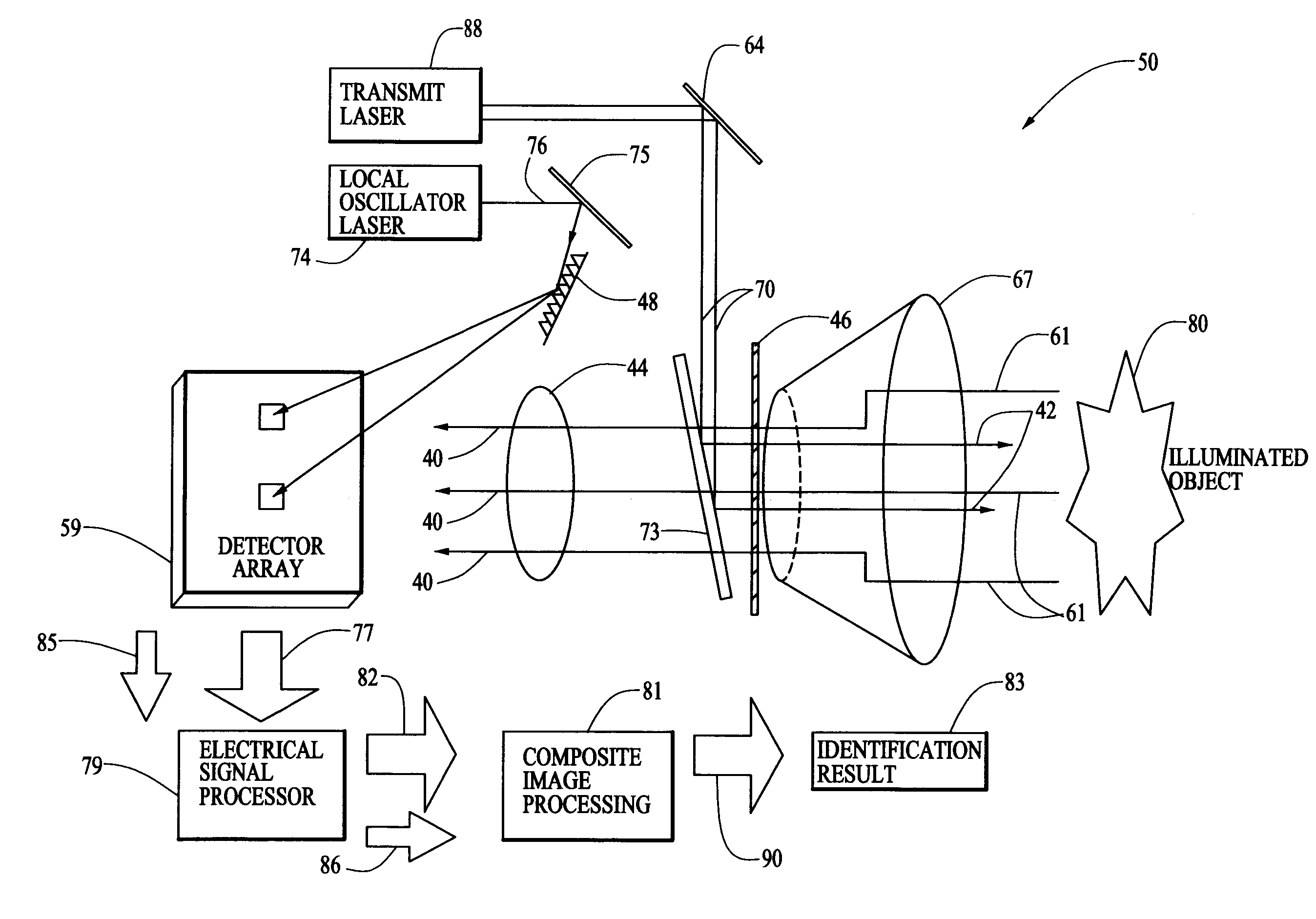
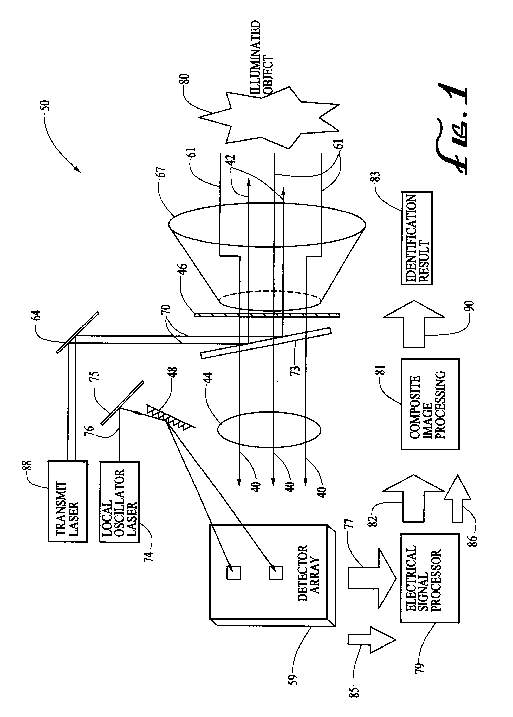
[0011]FIG. 1 depicts the preferred embodiment of the long range Combined Coherent and Incoherent Imaging LADAR system 50, where long range is the separation between the LADAR laser source and the object and is on the order of tens of kilometers.

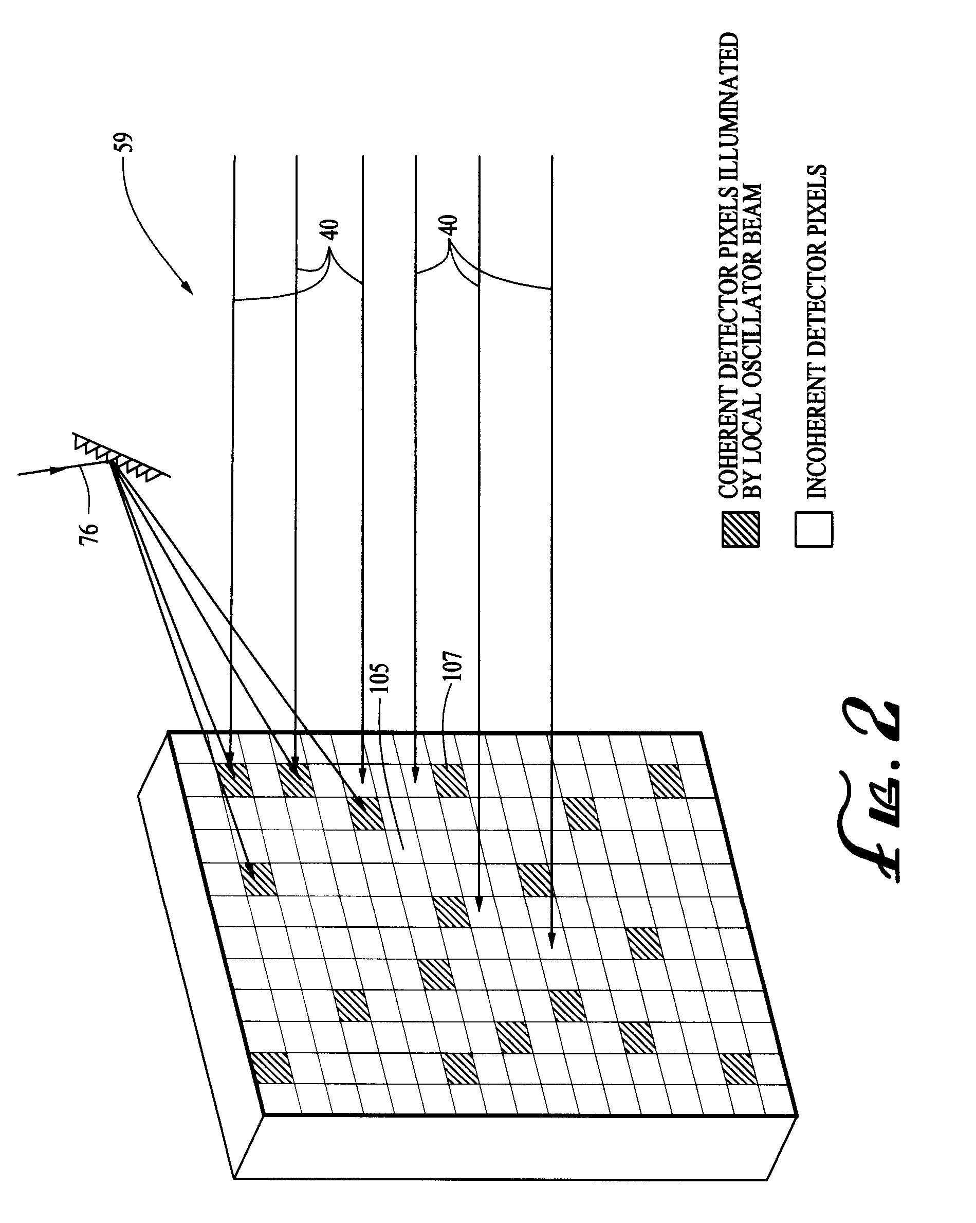
[0012]Referring to FIG. 1, a linearly polarized CW type laser source 74 is used to generate a Local Oscillator (LO) laser beam 76 which illuminates elements of the detector array 59 used for coherent detection. A linearly polarized transmit laser source 88 is used to generate a transmit beam 70 which is used to illuminate the object 80 to be identified. The transmit laser source 88 must provide either a modulated continuous wave (CW) or pulsed laser beam 70. Either a CW or pulsed laser source will produce the required signal to noise ratio for the waveform used to accurately measure range and micro Doppler information. Although a CW waveform measures unambiguous frequency information from the target, there are techniques using coherent pulse ...


PUM


Abstract

The present invention relates generally to a long range eye-safe laser radar (LADAR) system for use in an environment where real-time non-cooperative identification of an object is required. In particular, a laser beam is aimed at an object, the laser energy reflected from the object is collected by a detector array for use in generating a composite of both a high resolution 3-Dimensional (3D) shape of the object and the object's high resolution micro-Doppler vibration spectrum, a characteristic of the object as unique as a fingerprint. The composite is then used to automatically identify the object by comparison to a database of similar composite sets of 3D shape and vibration spectrum information with the results of the identification conveyed to the user.

Description

CROSS-REFERENCE TO RELATED APPLICATIONS[0001]This is a divisional application, claiming the benefit of a nonprovisional parent application Ser. No. 11 / 591,666 filed on Oct. 26, 2006.BACKGROUND OF THE INVENTION[0002]1. Field of the Invention[0003]The present invention relates generally to a long range eye-safe laser radar (LADAR) system for use in an environment where real-time non-cooperative identification of an object is required. In particular, a laser beam is aimed at an object, the laser energy reflected from the object is collected by a detector array for use in generating a composite of both a high resolution 3-Dimensional (3D) shape of the object and the object's high resolution micro-Doppler vibration spectrum, a characteristic of the object as unique as a fingerprint. The composite is then used to automatically identify the object by comparison to a database of similar composite sets of 3D shape and vibration spectrum information with the results of the identification conv...

Claims


Application Information

Patent Timeline
Patent Type & Authority Applications(United States)
IPC IPC(8): G01C3/08
CPCG01S7/4802G06K9/3241G01S17/89G01S17/58G06V10/255
Inventor HINTZ, ROBERT T.BUSER, RUDOLF G.
Owner USA REPRESENTED BY THE SEC OF THE NAVY
Why Eureka
Try Eureka