
Cancer treatment using selective photo-apoptosis

a technology of selective photoapoptosis and cancer, applied in the field of cancer treatment using selective photoapoptosis, can solve problems such as producing one or more undesired effects

Inactive Publication Date: 2011-02-17
PHOTOMETICS
View PDF94 Cites 8 Cited by
  • Summary
  • Abstract
  • Description
  • Claims
  • Application Information

AI Technical Summary

Benefits of technology

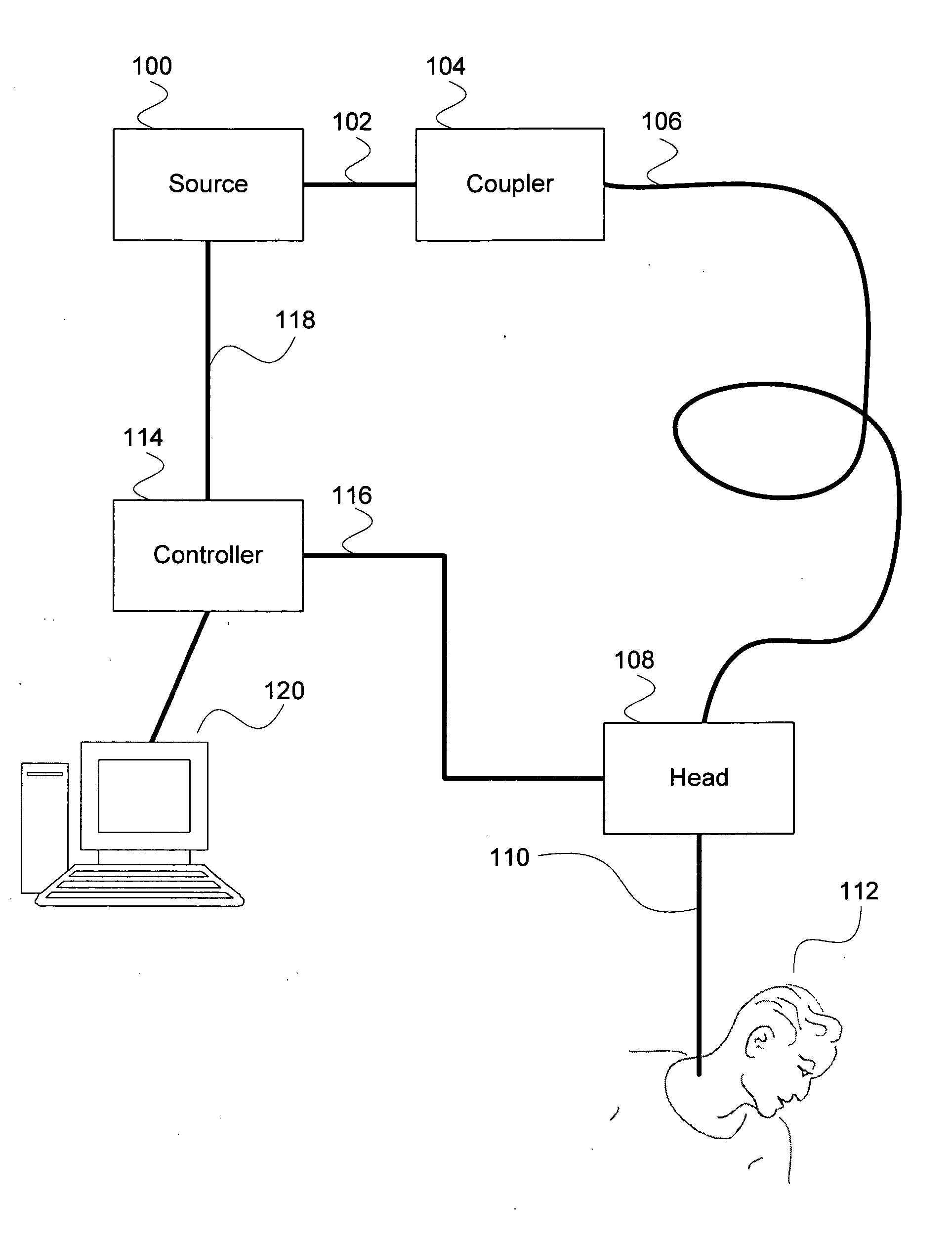
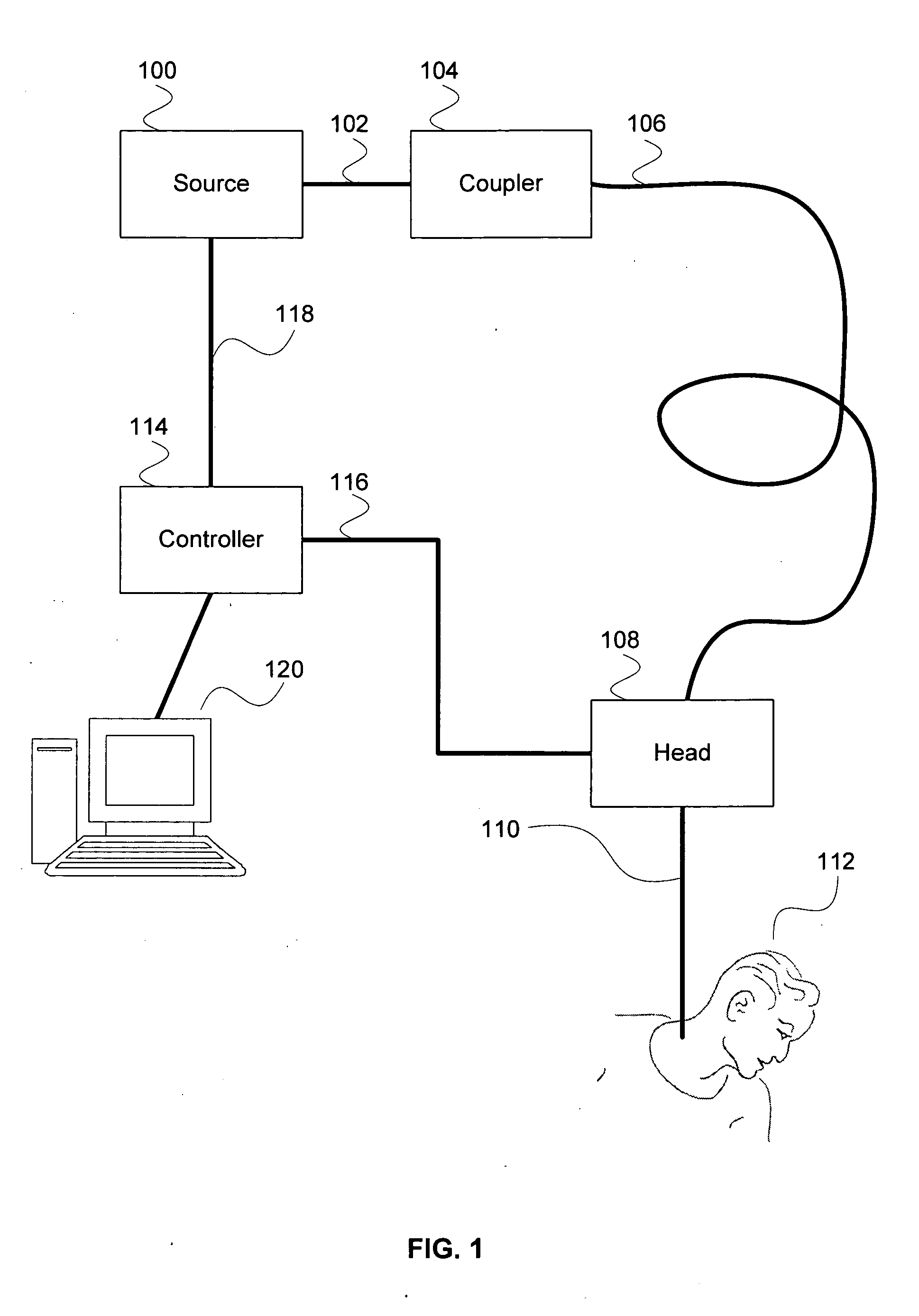
"The patent describes a system for cancer treatment using selective photo-apoptosis, which involves using light to stimulate the natural process of disposing of cancer cells. The system includes a source, a coupler, a head, a controller, and a scan pattern. The invention uses chemicals, drugs, or genetic manipulation to create a cancer treatment that stimulates apoptosis, which is a less toxic process than other therapies that involve necrosis. The invention aims to provide a safer and more effective treatment for cancer while minimizing damage to surrounding normal cells."

Problems solved by technology

However, these treatments generally produce one or more undesired effects such as: energy damage to neighboring healthy cells or tissues, damage to neighboring healthy cells or tissues through the release of internal cellular components and treatment byproducts, wounds requiring healing, and necrotic tissue that must be absorbed by the body.

Method used


Image

  • Cancer treatment using selective photo-apoptosis
  • Cancer treatment using selective photo-apoptosis
  • Cancer treatment using selective photo-apoptosis

Examples


Embodiment Construction

b class="d_n">[0011]FIG. 6 is a diagram illustrating an embodiment of a scan pattern.

[0012]FIG. 7 illustrates example spectra of a target and a host in one embodiment.

[0013]FIGS. 8-11 are tables illustrating embodiments of wavelengths to target for treatment.

[0014]FIG. 12 is a flow diagram illustrating an embodiment of a process for a system for selective photo-apoptosis cancer treatment.

[0015]FIG. 13 is a flow diagram illustrating an embodiment of a process for a system for selective photo-apoptosis cancer treatment.

[0016]FIG. 14 is a flow diagram illustrating an embodiment of a process for a system for selective photo-apoptosis cancer treatment.

[0017]FIG. 15 is a flow diagram illustrating an embodiment of a process for determining a selective photo-apoptosis treatment.

[0018]FIGS. 16A and 16B are flow diagrams illustrating embodiments of processes for a system for selective photo-apoptosis cancer treatment.

[0019]FIG. 17 is a flow diagram illustrating an embodiment of a process for ...


PUM


Abstract

A system for cancer treatment comprises a processor and a memory. The processor is configured to receive a target type and a host type and determine one or more illumination source characteristics such that: an illumination of the target type employing the one or more illumination source characteristics induces apoptosis in the target type without initiating thermolysis or ablation of the target type; and an illumination of the host type employing the one or more illumination source characteristics does not substantially induce apoptosis, thermolysis, or ablation in the host type. The memory is coupled to the processor and configured to provide the processor with instructions.

Description

CROSS REFERENCE TO OTHER APPLICATIONS[0001]This application is a continuation in part of co-pending U.S. patent application Ser. No. 12 / 057,042 entitled “Differential Photochemical and Photomechanical Processing” filed Mar. 27, 2008, which is incorporated herein by reference for all purposes; which is a continuation of U.S. patent application Ser. No. 10 / 789,948 (Now U.S. Pat. 7,354,433), entitled DISINFECTION, DESTRUCTION OF NEOPLASTIC GROWTH, AND STERILIZATION BY DIFFERENTIAL ABSORPTION OF ELECTROMAGNETIC ENERGY filed Feb. 26, 2004, which is incorporated herein by reference for all purposes; which claims priority to U.S. Provisional Application No. 60 / 450,736, entitled DISINFECTION, DESTRUCTION OF NEOPLASTIC GROWTH, AND STERILIZATION BY DIFFERENTIAL ABSORPTION OF ELECTROMAGNETIC ENERGY filed Feb. 28, 2003 which is incorporated herein by reference for all purposes.BACKGROUND OF THE INVENTION[0002]The development of cancer is associated with dysregulation of two common cell processe...

Claims


Application Information

Patent Timeline
Patent Type & Authority Applications(United States)
IPC IPC(8): A61B18/18
CPCA61B2018/2085A61L2/0011A61L2/0023A61N2005/067A61N5/0613A61N2005/063A61L2/085A61B2018/20351A61B2018/205547A61N5/067A61B2018/207
Inventor PIERCE, BRIAN
Owner PHOTOMETICS
Learn More