
System for electroporation therapy

a catheter system and electroporation therapy technology, applied in the field of catheter systems, can solve the problems of delayed therapeutic confirmation, inability to assess instantaneous success of electroporation therapy, and severe limitations of using electroporation therapy in ep applications, so as to improve the accuracy of electrode temperature measurement and increase the selectivity of what tissu

Active Publication Date: 2016-03-22
ST JUDE MEDICAL ATRIAL FIBRILLATION DIV
View PDF27 Cites 101 Cited by
  • Summary
  • Abstract
  • Description
  • Claims
  • Application Information

AI Technical Summary

Benefits of technology

[0013]One advantage of the methods and apparatus described, depicted and claimed herein relates to, in direction-sensitive electrode assembly embodiments for electroporation therapy, an increased selectivity in what tissue is subjected to the electroporation therapy. Another advantage of the methods and apparatus described, depicted and claimed herein relates to, in optical-based tissue sensing embodiments for electroporation therapy, an improved procedure for monitoring both the progress as well as the ultimate success of the therapy. A still further advantage of the methods and apparatus described, depicted and claimed herein relates to, in fiber optic temperature sensing embodiments, an improved accuracy in electrode temperature measurement by avoiding errors that would otherwise arise due to thermal sensor location eccentricity (as described in the Background) as well as providing immunity to RFI and EMI.

Problems solved by technology

Arrhythmia (i.e., irregular heart rhythm) can create a variety of dangerous conditions including loss of synchronous atrioventricular contractions and stasis of blood flow which can lead to a variety of ailments and even death.
Generally, for use in electrophysiological (EP) applications, the success of electroporation therapy cannot be assessed instantaneously, such as in RF ablation.
However, such delayed therapeutic confirmation poses a severe limitation in using electroporation therapy in EP applications.
In addition, another feature of known electroporation apparatus is that they are characterized by electrode assemblies that produce an omni-directional electric field, which may undesirably affect non-target tissue.
Because RF ablation may generate significant heat, which if not controlled can result in undesired or excessive tissue damage, such as steam pop, tissue charring, and the like, it is common to include a mechanism to irrigate the target area with biocompatible fluids, such as a saline solution.
However, the use of either thermocouples or thermistors has spatial limitations in terms of its placement in the electrode.
This off-center positioning of the thermal sensor is less than ideal since it could affect the temperature measurement.
Accordingly, these conventional arrangements are susceptible to radio-frequency interference (RFI) and / or electromagnetic interference (EMI) by virtue of at least these connecting wires.
Hence the use of thermal sensors to monitor the creation of tissue necrosis from electroporation is generally redundant.

Method used


Image

  • System for electroporation therapy
  • System for electroporation therapy
  • System for electroporation therapy

Examples


Embodiment Construction

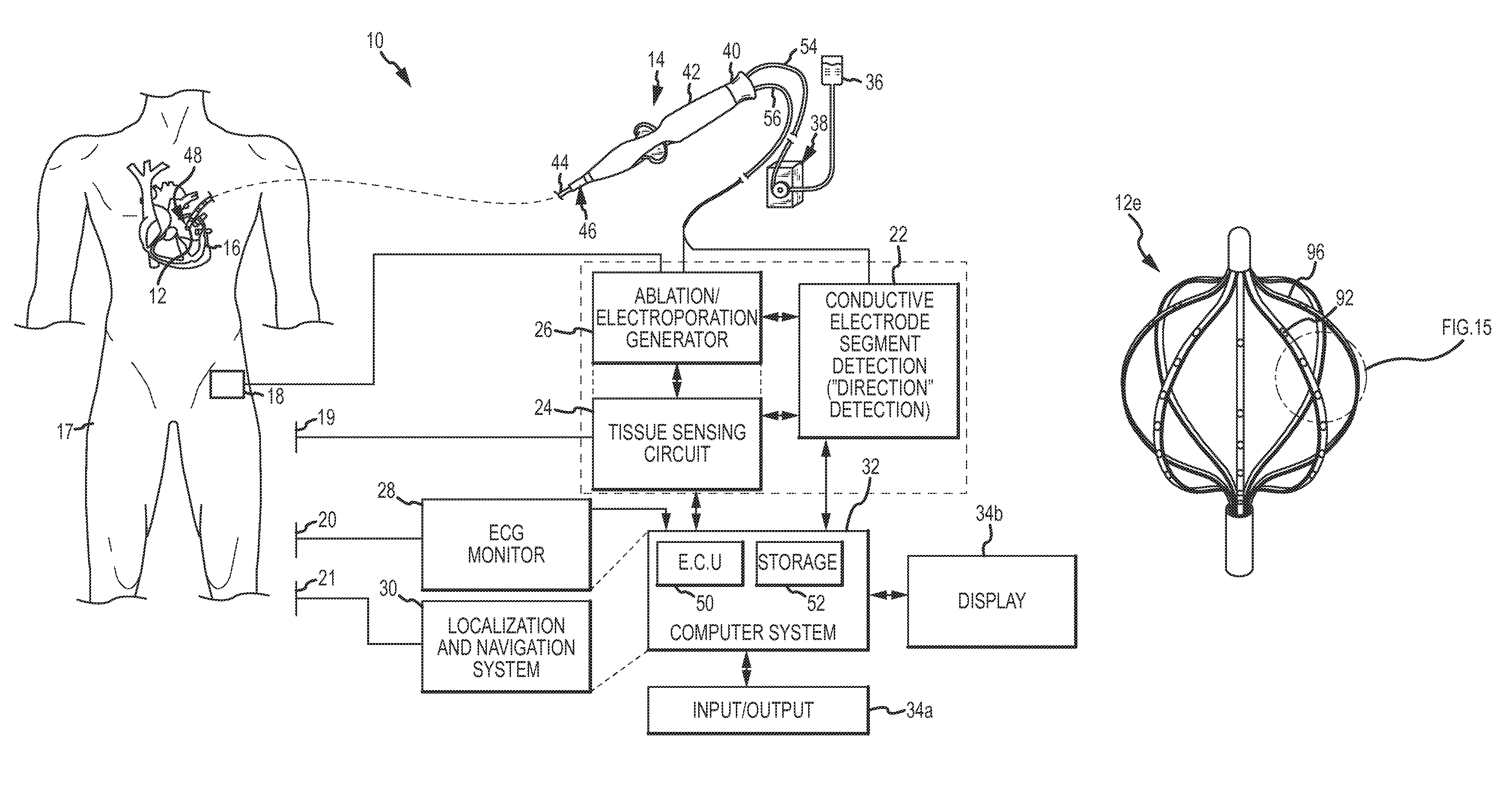
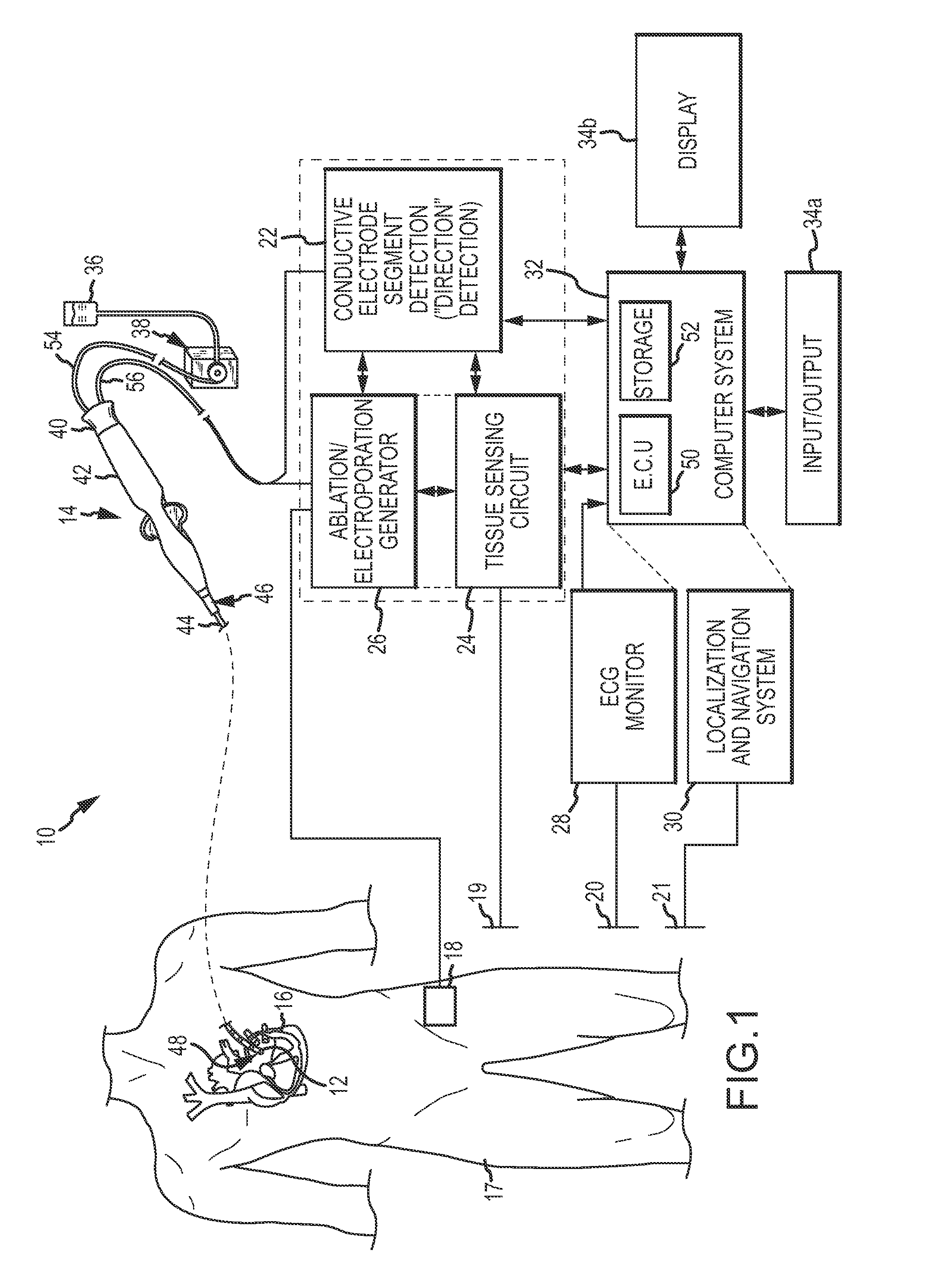
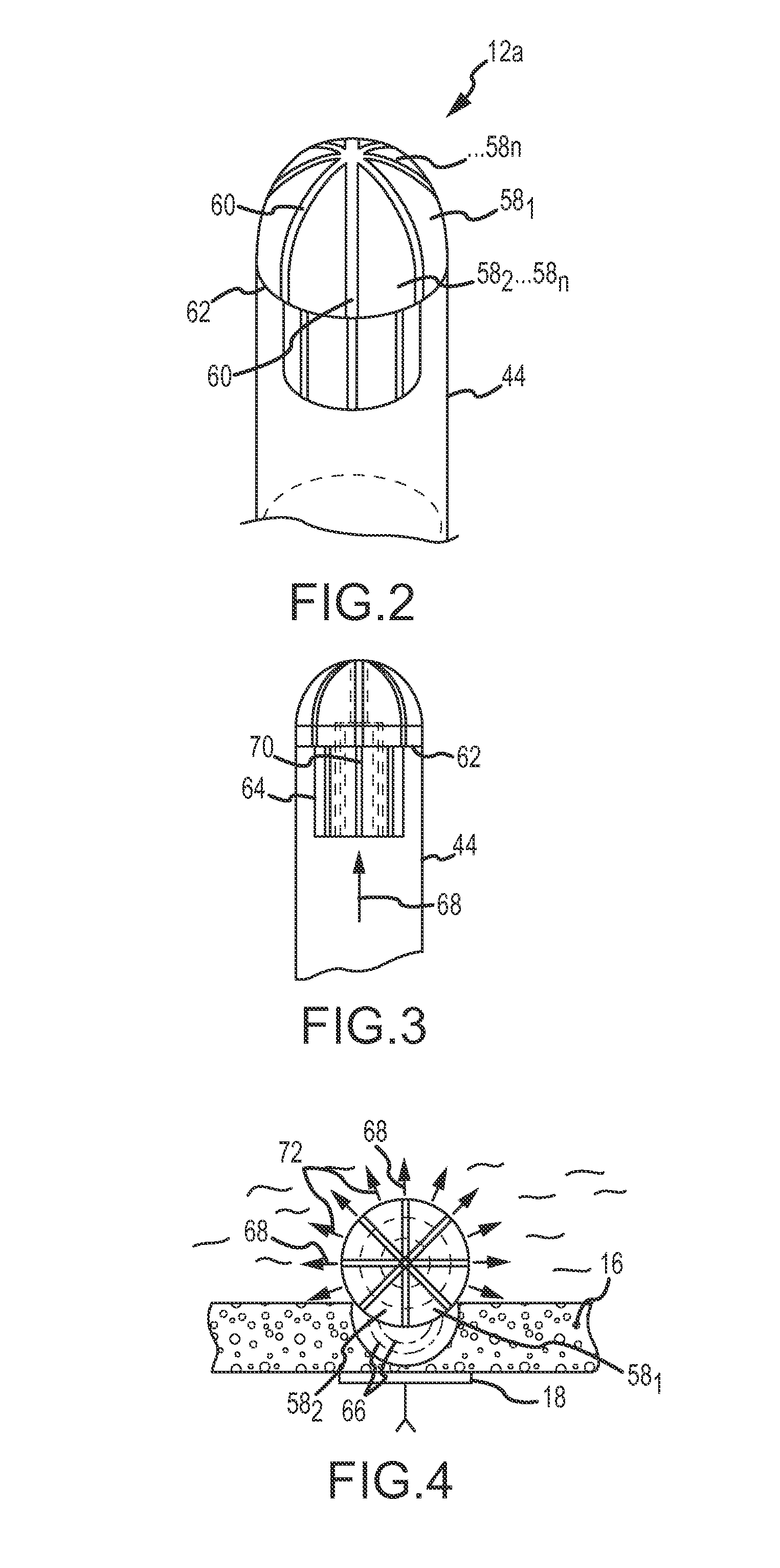
[0031]Referring now to the drawings wherein like reference numerals are used to identify identical components in the various views, FIG. 1 is a diagrammatic and block diagram view of a system 10 in connection with which direction-sensitive multi-polar or multi-array electrode assemblies for electroporation therapy may be used. In general, the various embodiments include an electrode assembly disposed at the distal end of a catheter. The electrode assembly comprises a plurality of individual, electrically-isolated electrode elements. Each electrode element is individually wired such that it can be selectively paired or combined with any other electrode element to act as a bipolar or a multi-polar electrode for both sensing (more below) and electroporation energization purposes. FIGS. 2-17 show various embodiments featuring direction-sensitive multi-polar or multi-array electrode assemblies. In the sensing mode, the electrode elements are electrically scanned to detect or identify whi...


PUM


Abstract

Catheter systems include direction-sensitive, multi-polar tip electrode assemblies for electroporation-mediated therapy, electroporation-induced primary necrosis therapy and electric field-induced apoptosis therapy, including configurations for producing narrow, linear lesions as well as distributed, wide area lesions. A monitoring system for electroporation therapy includes a mechanism for delivering electrochromic dyes to a tissue site as well as a fiber optic arrangement to optically monitor the progress of the therapy as well as to confirm success post-therapy. A fiber optic temperature sensing electrode catheter includes a tip electrode having a cavity whose inner surface is impregnated or coated with thermochromic / thermotropic material that changes color with changes in temperature. An optic fiber / detector arrangement monitors the thermochromic or thermotropic materials, acquiring a light signal and generating an output signal indicative of the spectrum of the light signal. An analyzer determines an electrode temperature based on the detector output and predetermined spectrum versus temperature calibration data.

Description

CROSS-REFERENCE TO RELATED APPLICATIONS[0001]Not applicable.BACKGROUND OF THE INVENTION[0002]a. Field of the Invention[0003]The instant invention relates generally to catheter systems.[0004]b. Background Art[0005]It is generally known that ablation therapy may be used to treat various conditions afflicting the human anatomy. One such condition that ablation therapy finds a particular application is in the treatment of atrial arrhythmias, for example. When tissue is ablated, or at least subjected to ablative energy generated by an ablation generator and delivered by an ablation catheter, lesions form in the tissue. Electrodes mounted on or in ablation catheters are used to create tissue necrosis in cardiac tissue to correct conditions such as atrial arrhythmia (including, but not limited to, ectopic atrial tachycardia, atrial fibrillation, and atrial flutter). Arrhythmia (i.e., irregular heart rhythm) can create a variety of dangerous conditions including loss of synchronous atrioven...

Claims


Application Information

Patent Timeline
Patent Type & Authority Patents(United States)
IPC IPC(8): A61B18/18A61N1/32A61B18/14A61B18/00
CPCA61N1/327A61B18/14A61B2018/0016
Inventor PAUL, SAURAVTEGG, TROY T.BYRD, ISRAEL A.THAO, RIKIPURYEAR, HARRY A.NEMEC, LINDABERNS, JOHN M.
Owner ST JUDE MEDICAL ATRIAL FIBRILLATION DIV
Learn More