Communication process for elements composing a home or industrial electrical energy distribution network and devices for implementing the same

a technology of communication process and electrical energy distribution network, applied in the direction of power network operation system integration, transmission, liquid/fluent solid measurement, etc., can solve the problems of not allowing the design of a full and programmable solution, complex and expensive, and not integrating known solutions

Active Publication Date: 2011-02-17
KOGLER ROLAND +1
View PDF11 Cites 16 Cited by
  • Summary
  • Abstract
  • Description
  • Claims
  • Application Information

AI Technical Summary

Benefits of technology

[0105]In addition to that connection to the INTERNET network, it should be noticed that, and that is already a significant advantage of the present invention, two particular elements composing the electrical energy distribution network can fully communicate, thus allowing the association procedure described hereinafter.
[0106]FIG. 1b illustrates an example of one association procedure between a switch communicating with another element, such as a light for example.
[0107]The process starts with a step 1010 corresponding to the entering into a so-called “configuration” mode by switch 114. In one embodiment, such configuration mode is started after, for instance, a series of ten switch on-switch off controlled by the user, thus resulting in the switch entering into the configuration mode.
[0108]The process then proceeds with a step 1020, wherein the second communicating component—such as a light connection device (DCL) 131—is set in a similar “configuration” mode. This can be done, for instance, by any particular arrangement, such as a specific push button controlling the entering into the configuration mode.
[0109]In a step 1030, the two elements exchange their IP addresses for the purpose of generating an association between them.
[0110]Optionally, in a step 1040, information of association are transmitted by broadcast to the electrical energy distribution network in order to allow a backup of this association in one or several central points.

Problems solved by technology

But this patent, and many others, does not suggest to incorporate the IP communication within the electrical energy distribution network, and particularly the different components composing such networks.
However, such solution does not allow the design of a full and programmable solution of the different components and modules constituting the electrical panel in the house.
Although all those solutions provide significant improvement to home automation, and clearly show the critical interest of manufacturers for such field, it should be noticed that the known solutions do not integrate the IP protocol within the electrical energy distribution network.
Nevertheless, while all those prior art techniques clearly demonstrate the high interest shown by the manufacturers, those solutions remain complex and expensive and, moreover, leave the end-user totally dependent on the technical choices of one particular and “proprietary” architecture provided by one manufacturer, which is a serious disadvantage when it comes to achieve—and maintain—the installation of an effective and long lasting electrical energy distribution network.

Method used


Image

  • Communication process for elements composing a home or industrial electrical energy distribution network and devices for implementing the same
  • Communication process for elements composing a home or industrial electrical energy distribution network and devices for implementing the same
  • Communication process for elements composing a home or industrial electrical energy distribution network and devices for implementing the same

Examples


first embodiment

I. First Embodiment

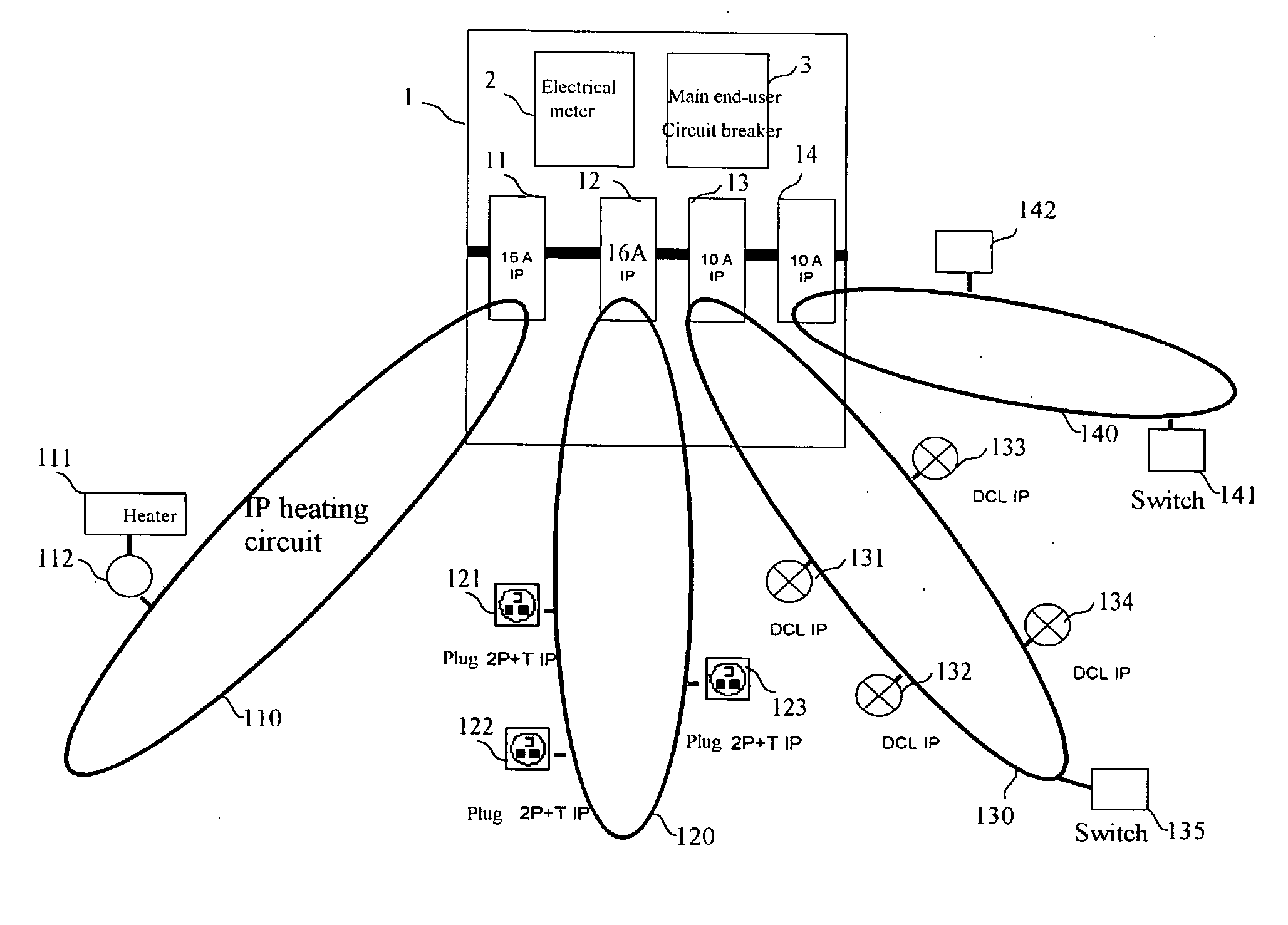
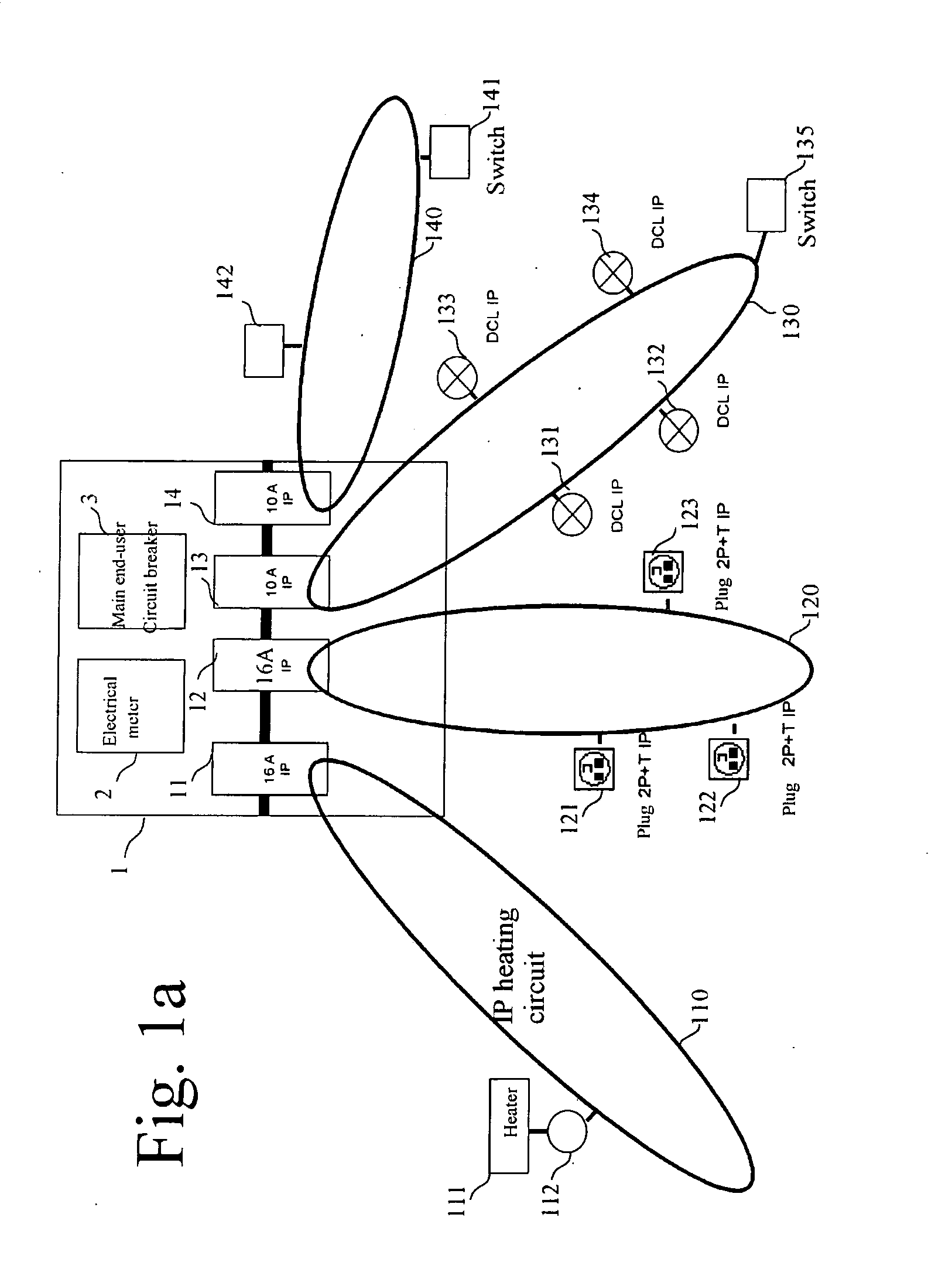
[0147]The first embodiment which is described and discussed below is particularly adapted to the implementation of the invented process to a “basic” installation for the purpose of achieving a home electrical energy distribution network, taking advantage of new functionalities resulting from the capability of communication of the device, modules and components constituting the communicating electrical energy distribution network described above.

[0148]FIG. 6A illustrates this first embodiment in which the electrical network, in its entirety, is a unique LAN network where all constituents have their own IP address and can thus communicate with any other component of the network.

[0149]In this first embodiment, each component (circuit breaker, two-wires+ground plug 2P+T, light connection device DCL etc . . . ) gets its IP address through a protocol of address assignment. In a particular embodiment, the assignment of the IP address complies with the following protocols...

second embodiment

II. Second Embodiment

[0164]FIG. 7 illustrates a second embodiment more advantageous and sophisticated which is particularly suited to complex installations, such as industrial installations.

[0165]Indeed, in complex installations, the number of components of the electrical network can become very important and, therefore, difficult to manage for the end-user.

[0166]Moreover, it can be desirable to improve the possibilities of control of the different components constituting the electrical energy distribution network and, for that purpose, it may be desirable to divide one given energy distribution network in sub-systems or sub-networks, each corresponding to one circuit line or to a set of circuit lines for example.

[0167]One embodiment of the present invention allows, and this is a significant advantage, to divide and share the energy distribution network (because it is only made of two conductors PHASE and NEUTRAL in the case of a single-phase network) so that it no longer correspond...


PUM


Abstract

A communication process between two constitutive elements of the network of electricity distribution in a domestic or industrial premise including circuit breakers, electrical modules, switches, electrical plugs and light connection devices. The process including the following steps: assignment by a protocol such as DHCP, BootP or RARP of a first IP address to a first element of the power distribution network, assignment of a second IP address to a second element, and establishment of a communication between the first and second elements of the power distribution network.

Description

TECHNICAL FIELD OF INVENTION[0001]The present invention concerns electrical energy distribution networks for home and industrial premises and more particularly a communication process for elements composing a home or industrial electrical energy distribution network.BACKGROUND[0002]The development of home automation has resulted in on-going investigations for increasing the intelligence of components composing the electrical energy distribution network, particularly in household.[0003]For that purpose, searches were conducted for using the functionalities provided by the Internet network in order to increase the intelligence of the electrical appliances which are likely to be connected to the electrical energy distribution network.[0004]European patent EP1217475 describes a device and a procedure of remote control of appliances based on the integration of a web server in the appliance and the connection of this server to an (ISP) Internet Service Provider. But this patent, and many ...

Claims


Application Information

Patent Timeline
Patent Type & Authority Applications(United States)
IPC IPC(8): G06F1/28G06F1/26
CPCY04S40/162H04L12/2818H04L2012/2843H04B2203/5458H04B2203/5408Y02B70/325H04L2012/285Y04S20/228H04B3/542H04L29/12216H04L41/0806H04B2203/5445H04B2203/5454H04L61/2015H04L12/2807Y04S40/00H04L61/5007H04L61/5014Y02B70/30Y04S20/20
Inventor KOGLER, ROLANDSCHUFFENECKER, THIERRY
Owner KOGLER ROLAND
Why Eureka
Try Eureka