Insect trap

Active Publication Date: 2011-02-24
BRANDENBURG
View PDF10 Cites 26 Cited by
  • Summary
  • Abstract
  • Description
  • Claims
  • Application Information

AI Technical Summary

Benefits of technology

[0027]According to a third and independent aspect of the present invention there is also provided an insect catching means comprising at least two insect capture surfaces, a first surface of which is one colour or shade, and a second surface, which is designed to facilitate ease of counting and or identification of captured insects, which is a different colour or shade to the first surface.
[0028]Preferably the second surface can be easily detached from the first surface for record keeping, there being a line of weakening e.g. perforation, between the fir

Problems solved by technology

The lights also need to be cleaned as insects get “welded” to the bulbs and in any case, the lights have a limited life span.
Additio

Method used


Image

  • Insect trap
  • Insect trap
  • Insect trap

Examples


Embodiment Construction

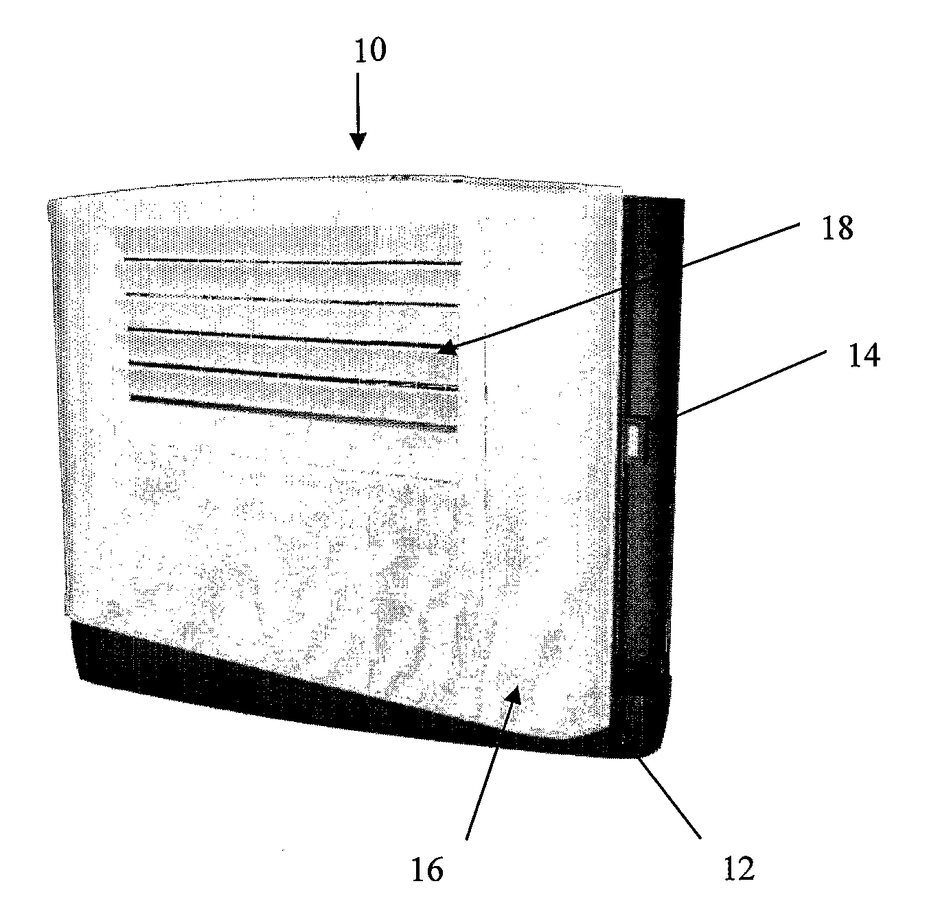
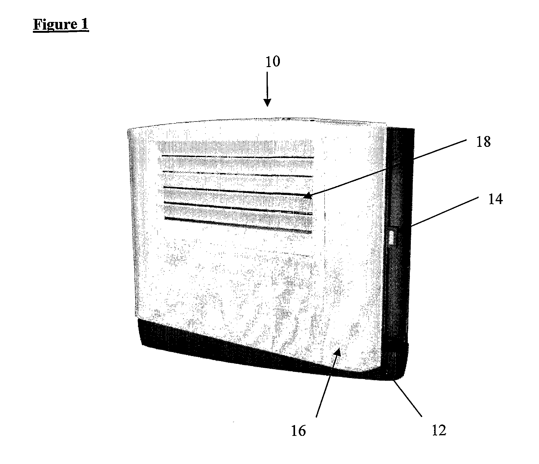
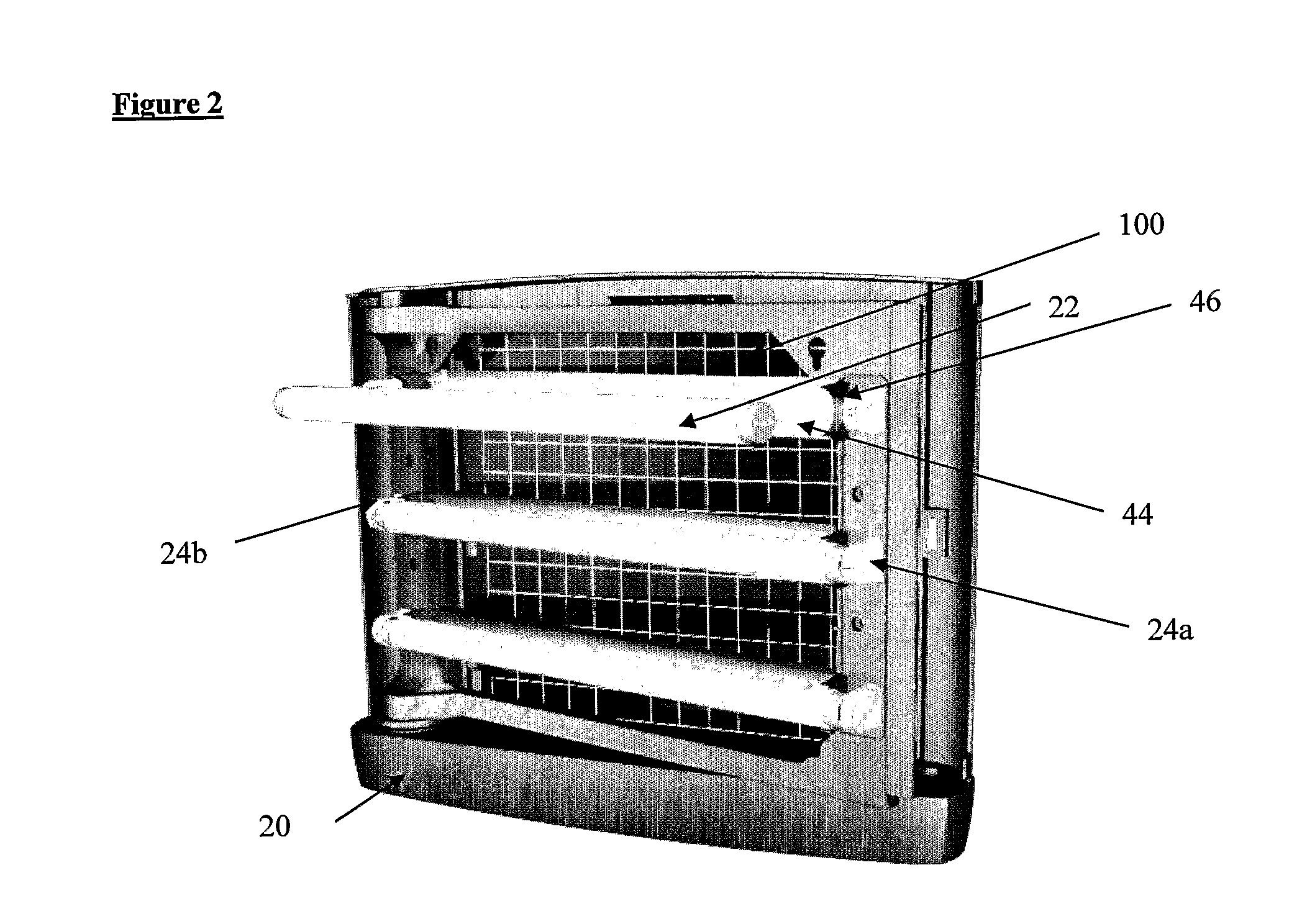
[0043]Referring to the Figs an insect trap (10) according to a first aspect of the invention comprises three basic components: a back housing (12); a frame (14) and a cover (16). These are clearly illustrated in FIG. 5. The frame (14) is a perimeter frame (FIG. 3), comprising upper (14a) and lower (14b) frame members and two side members (14c; 14d). The perimeter frame (14) is swing, swivel or hinge mounted to the back housing (12) via a swing mechanism (20) which is substantially hidden (FIG. 2).

[0044]A plurality of 15 W or 25 W UV lights (22), three are illustrated in the example, are connected to paired electrical fittings (24a; 24b) (FIG. 2), and wiring (not shown) runs in channels or conduits (not shown) which are sealed by rubber or silicon gaskets (not shown) and enclosed by fascia plates (26) (FIG. 3) which are preferably metallic such that they provide rigidity to the moulded plastics frame. The metal also allows the frame to be held shut against a magnetic contact (28) pro...


PUM


Abstract

The invention relates to an insect trap which has been designed to facilitate simple and efficient servicing, maintenance and cleaning. The trap includes a back housing; a frame swing mounted to said housing; and a cover comprising openings allowing insects to enter the trap and the frame supports at least one light such that said frame and lights can be moved from a first position where they overlie the back housing, to a second position where they lie clear of the back housing such that an insect catching means which may be fitted over the back housing is readily accessible for replacement during servicing. Additionally, the trap is adapted for ease of servicing and jet cleaning by the provision of shields each of which sealably protect, from water ingress, the plurality of lights at the positions where they connect to electrical fittings.

Description

TECHNICAL FIELD[0001]The present invention relates to an insect trap and more particularly to an insect trap which has been designed to facilitate simple and efficient servicing, maintenance and cleaning.BACKGROUND OF THE INVENTION[0002]Insect traps of various types are well known. A particularly common trap type, particularly for flying insects, comprises an insect attractant means, such as, for example a UV light source and an insect trapping means, such as, for example an adhesive board or paper contained in a housing. The flying insects are attracted to the trap, enter the housing through openings and get caught on the trapping means. To maintain efficiency of capture, the adhesive board or paper needs to be regularly replaced and the trap cleaned. The adhesive board or paper also needs to be inspected and records kept. The lights also need to be cleaned as insects get “welded” to the bulbs and in any case, the lights have a limited life span.[0003]The traps are often fitted out...

Claims


Application Information

Patent Timeline
IPC IPC(8): A01M1/04A01M1/14
CPCA01M1/145A01M1/04A01M1/16A01M1/02A01M2200/01A01M1/026A01M1/08A01M99/00F21V23/06F21V31/005
Inventor WILLCOX, JOHN CADMANKAYE, MATTHEW VARGHESE
Owner BRANDENBURG
Why Eureka
Try Eureka