Low differential temperature rotary engines

Inactive Publication Date: 2011-02-24
DYVERGA ENERGY CORP
View PDF22 Cites 21 Cited by
  • Summary
  • Abstract
  • Description
  • Claims
  • Application Information

AI Technical Summary

Benefits of technology

[0027]In some embodiments, at least one of the vessels has fins thereon to facilitate t

Problems solved by technology

Extraction of energy from low differential temperature sources, such as water heated by solar, geothermal, or industrial processes, and conversion of this energy to rotational or other forms of energy is often in

Method used


Image

  • Low differential temperature rotary engines
  • Low differential temperature rotary engines
  • Low differential temperature rotary engines

Examples


Embodiment Construction

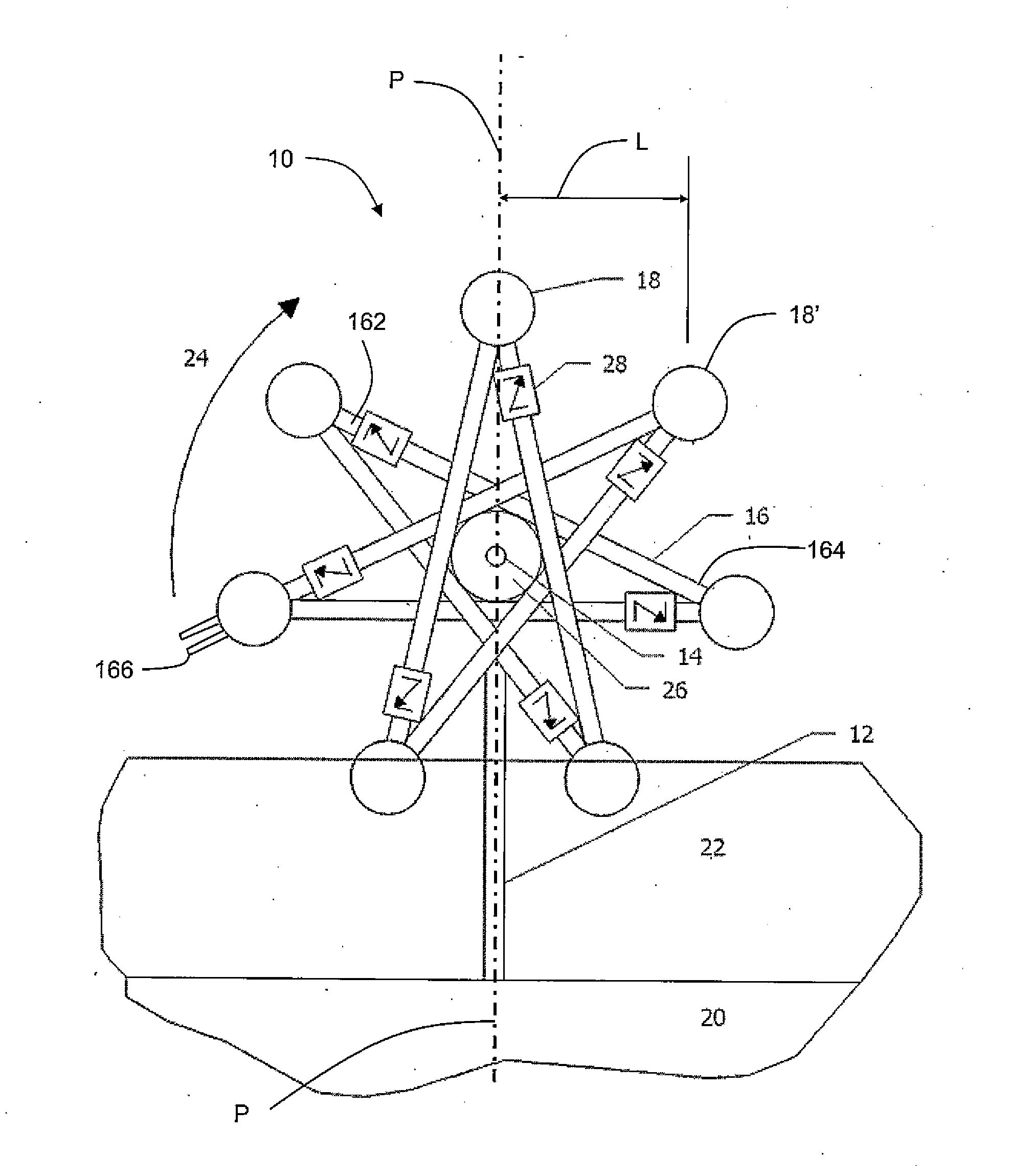
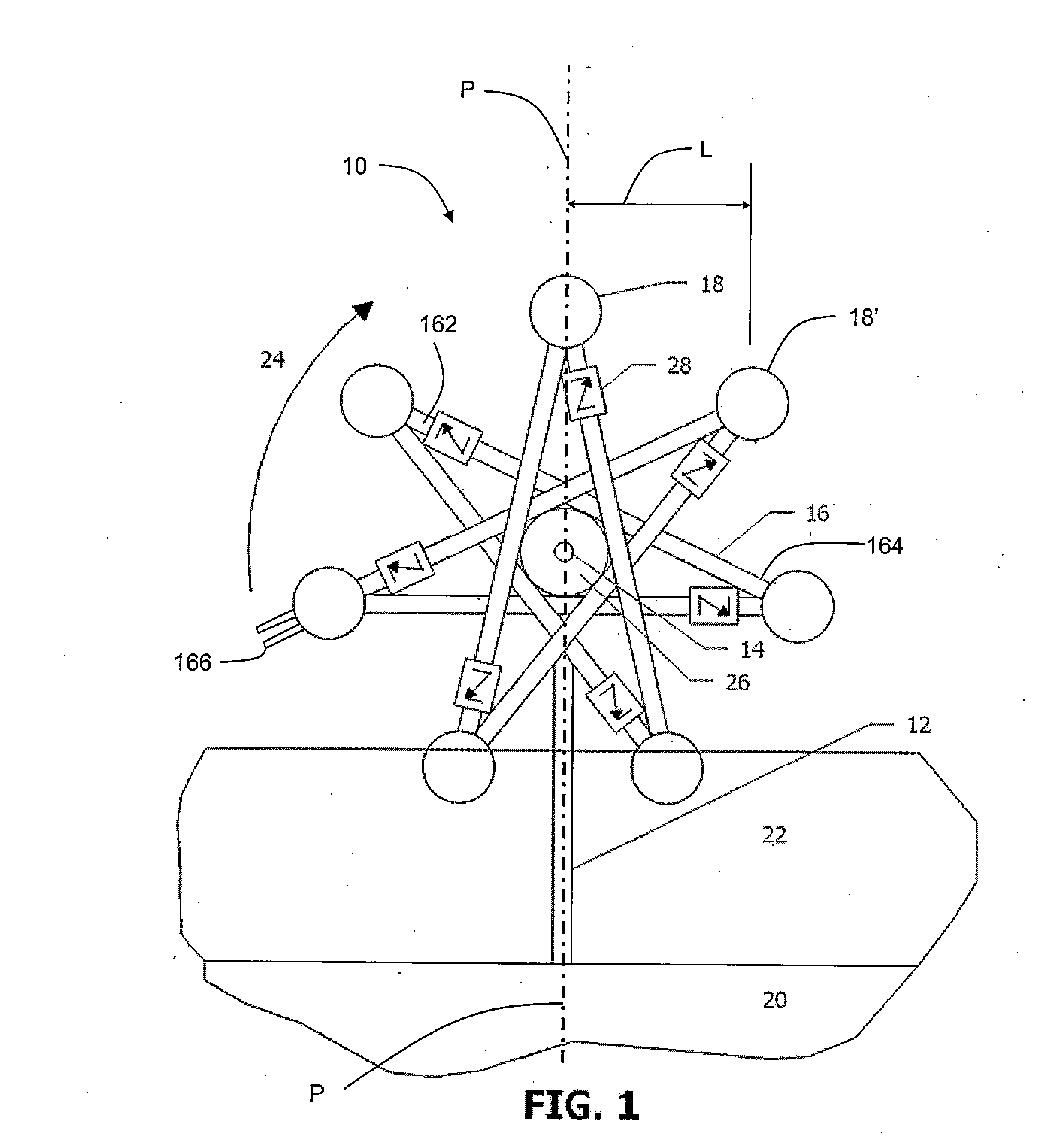
[0058]Turning now to FIG. 1, illustrated therein is an engine according to one embodiment. The engine generally includes a support 12 a shaft 14, and a plurality of vessels 18 interconnected together by conduits 16 in a spaced relationship about the shaft 14.

[0059]As shown, the support 12 generally extends upwardly from and may be affixed to a base 20, such as the bottom of a tank or a ground surface. Alternatively, the engine 10 could also be supported from other directions (e.g. from above or suspended from an elevated surface, such as by using brackets).

[0060]Provided near the base 20 is a heat source 22, which could be a liquid heat source. In some embodiments, the heat source 22 may be at rest (e.g. the liquid is still) or the heat source 22 be flowing (e.g. the liquid is moving). Some examples of heat sources 22 could include water or other liquids warmed by industrial or residential processes (e.g. warm waste water), solar heating, geothermal heating, ocean thermal heating, b...


PUM


Abstract

An engine for extracting energy from a heat source, comprising a support, a shaft rotatably coupled to the support and being rotatable in a first direction, a plurality of vessels coupled to and spaced about the shaft, a working fluid provided in the plurality of vessels, and a plurality of conduits connecting the vessels together in a circuitous fluid circuit. Each conduit has an outlet end connected to one of the plurality of vessels, an inlet end connected to another one of the plurality of vessels, and a one-way check valve configured to allow the working fluid to flow out of the one vessel via the outlet end, through the conduit and into the another vessel via the inlet end. The plurality of vessels and conduits are shaped and arranged about the shaft and the working fluid is selected so that when the one vessel is heated by the heat source the working fluid in the one vessel experiences an increase in vapour pressure causing at least part of the working fluid to flow from the one vessel into the another vessel located above the one vessel so as to produce a gravitational moment that encourages rotation of the shaft in the first direction.

Description

TECHNICAL FIELD[0001]The embodiments described herein relate to extracting energy from low differential temperature sources, and more specifically, to systems, apparatus, and methods for generating power from low differential temperature sources.INTRODUCTION[0002]Extraction of energy from low differential temperature sources, such as water heated by solar, geothermal, or industrial processes, and conversion of this energy to rotational or other forms of energy is often inefficient or impractical.[0003]A number of attempts have been made to provide apparatus that make the energy extraction more practical. For example, Gould (U.S. Pat. No. 4,570,444) describes a solar-powered motor with a wheel-like rotor having a rim separated into hollow compartments. The rotor is designed to revolve around a horizontal axis while containing a volatile liquid in some of its rim compartments. The rotor has a hub, also with separate compartments, and hollow spokes interconnecting the hub with the rim ...

Claims


Application Information

Patent Timeline
IPC IPC(8): F03G3/04
CPCF03G7/10F03G7/06F01K11/04F01K27/005F01K7/36F03G3/08Y02E60/16F03G7/06113F03G7/129
Inventor GODWIN, HAROLD EMERSON
Owner DYVERGA ENERGY CORP
Why Eureka
Try Eureka