Sliding Sleeve Locking Mechanisms

a locking mechanism and sliding sleeve technology, applied in the direction of fluid removal, wellbore/well accessories, construction, etc., can solve the problems of the sleeve within the sleeve valve, unwobbly, etc., and achieve the effect of preventing inadvertent operation

Active Publication Date: 2011-02-24
BAKER HUGHES INC
View PDF51 Cites 39 Cited by
  • Summary
  • Abstract
  • Description
  • Claims
  • Application Information

AI Technical Summary

Benefits of technology

[0006]The devices and methods of the present invention provide systems and methods for locking a sliding sleeve valve in

Problems solved by technology

These tools may inadvertently shift the sleeve

Method used


Image

  • Sliding Sleeve Locking Mechanisms
  • Sliding Sleeve Locking Mechanisms
  • Sliding Sleeve Locking Mechanisms

Examples


Embodiment Construction

[0029]As used in the discussion herein, the terms “up,”“down,”“upper,”“lower,”“above,”“below,”“upwardly,”“downwardly,” as well as other terms and their respective derivations, refer to relative, rather than absolute positions or orientations. Those of skill in the art will understand that various components and assemblies used within the described sliding sleeve locking assemblies may be reversed within a sliding sleeve valve and still provide desired function.

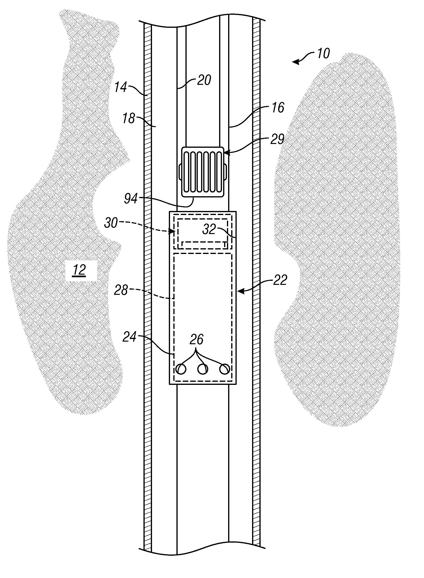
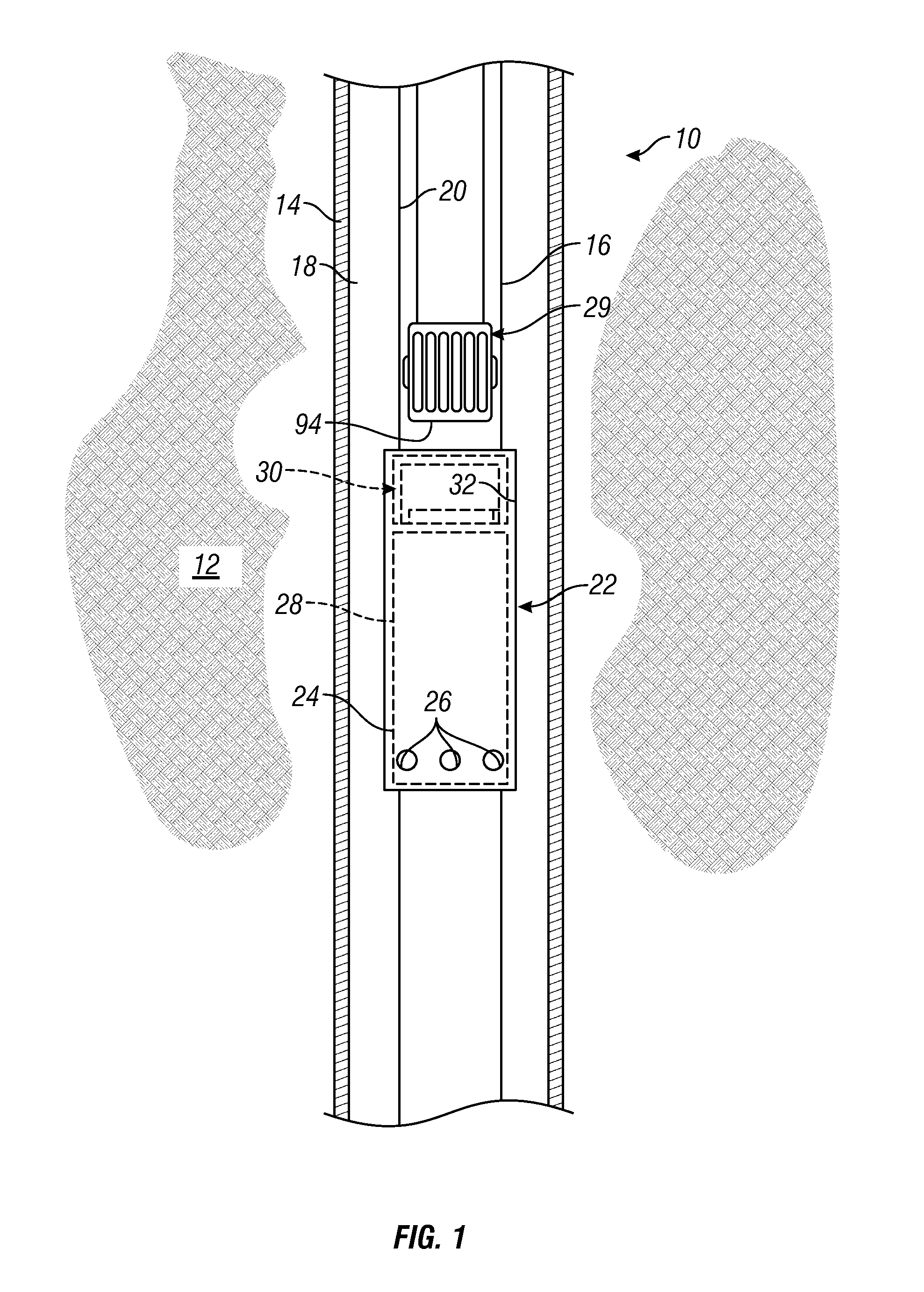
[0030]FIG. 1 illustrates a portion of an exemplary wellbore 10 that has been drilled through the earth 12 and which has been lined with casing 14. A production tubing string 16 is shown disposed within the wellbore 10. An annulus 18 is defined radially between the production tubing string 16 and the casing 14. The production tubing string 16 may be formed of a number of production tubing sections, of a type known in the art, which are interconnected to one another in an end-to-end fashion. The sections may be interconnected us...


PUM


Abstract

Systems and methods for locking a sliding sleeve valve in an open position and/or a closed position to prevent inadvertent operation of the sleeve valve during other operations.

Description

BACKGROUND OF THE INVENTION[0001]1. Field of the Invention[0002]The present invention generally relates to the design of sliding sleeve valves. In particular aspects, the invention relates to systems and methods for securing a sliding sleeve valve in an open or closed position.[0003]2. Description of the Related Art[0004]Sliding sleeve valves are used extensively in hydrocarbon production wellbores. A sliding sleeve valve generally includes an outer housing that defines a central flowbore. The housing has one or more lateral fluid flow ports defined therein. A sleeve member is disposed within the flowbore and is axially moveable with respect to the housing between a first position, wherein the one or more lateral fluid ports is blocked, and a second position, wherein the one or more fluid ports is open.[0005]In situations wherein a sleeve valve is incorporated into a production tubing string or other work string, wireline tools are often passed down through the center of those strin...

Claims


Application Information

Patent Timeline
IPC IPC(8): E21B34/14E21B34/00
CPCE21B2034/007E21B34/14E21B34/00E21B2200/06
Inventor CHAMBERS, CLAYJACOB, JOBBY T.CLEM, NICHOLAS J.FIGUEROA, HUGOCOCHRAN, TRAVIS E.
Owner BAKER HUGHES INC
Why Eureka
Try Eureka