
Inkjet recording apparatus and inkjet recording method

a recording apparatus and inkjet technology, applied in the direction of printing, other printing apparatus, etc., can solve the problems of suction marks being especially liable to occur in the leading end portion of the recording medium, affecting image quality, etc., and achieve the effect of prolonging suction time and preventing depression

Active Publication Date: 2011-02-24
FUJIFILM CORP
View PDF2 Cites 28 Cited by
  • Summary
  • Abstract
  • Description
  • Claims
  • Application Information

AI Technical Summary

Benefits of technology

[0012]According to this aspect of the invention, in a conveyance device, a recording medium is held by suctioning via suction holes on the opposite side of the medium to the surface where an image is formed, and the locations of the recording medium which are suctioned by the suction holes are changed. Consequently, even if the suction time is long, the same locations of the recording medium are not suctioned consecutively, and therefore it is possible to prevent depressions occurring in the image due to the suctioning via the suction holes. Furthermore, since the suction locations are changed at a prescribed interval, then it is possible to shorten the time during which the recording medium is suctioned in the same positions. Consequently, it is possible to cause the depressions in the recording medium to revert their shape when the suction locations are changed, and therefore the occurrence of depressions in the image due to the suction holes can be prevented during the whole image forming process.
[0047]According to inkjet recording apparatuses and inkjet recording methods of the present invention, when a recording medium is conveyed while being suctioned, since the recording medium is conveyed while changing the locations of the recording medium which are suctioned, then it is possible to prevent the occurrence of depressions in the image arising due to suctioning of the suction holes as a result of a prolonged suction time.

Problems solved by technology

If the medium is suctioned in this state, then the portions of the image area where the suction holes are disposed become depressed, and since the image area is dried in this state, then the depressions in the suction hole portions remain as suction marks after recording, thus leading to a problem of impaired image quality.
Moreover, Japanese Patent Application Publication No. 2009-35010 does not recognize the problems relating to depressions (suction marks) which are created by the suction holes, and suction marks have been especially liable to occur in the leading end portion of the recording medium which is suctioned first.

Method used


Image

  • Inkjet recording apparatus and inkjet recording method
  • Inkjet recording apparatus and inkjet recording method
  • Inkjet recording apparatus and inkjet recording method

Examples


first embodiment

General Composition of Inkjet Recording Apparatus

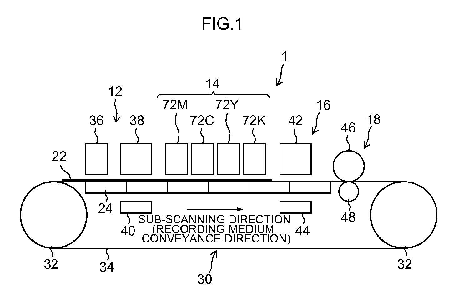
[0063]FIG. 1 is a general schematic drawing of an inkjet recording apparatus relating to a first embodiment of the present invention. The inkjet recording apparatus 1 shown in FIG. 1 is a belt conveyance type of inkjet recording apparatus and principally comprises a treatment liquid deposition unit 12, an image formation unit 14, a drying unit 16 and a fixing unit 18, and the recording medium 22 is conveyed by a suction belt conveyance apparatus 30.

[0064]The suction belt conveyance apparatus 30 comprises a pair of rollers 32 and an endless belt 34 wrapped about these rollers 32, at least one of the pair of rollers 32 is driven to rotate by a motor, or the like, which is not illustrated. Accordingly, the belt 34 travels in revolution about the pair of rollers 32.

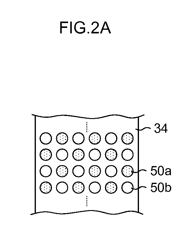
[0065]The belt 34 has a width greater than the width of the recording medium 22, and a plurality of suction holes 50 are formed in the upper surface of the belt 34. A suction c...

second embodiment

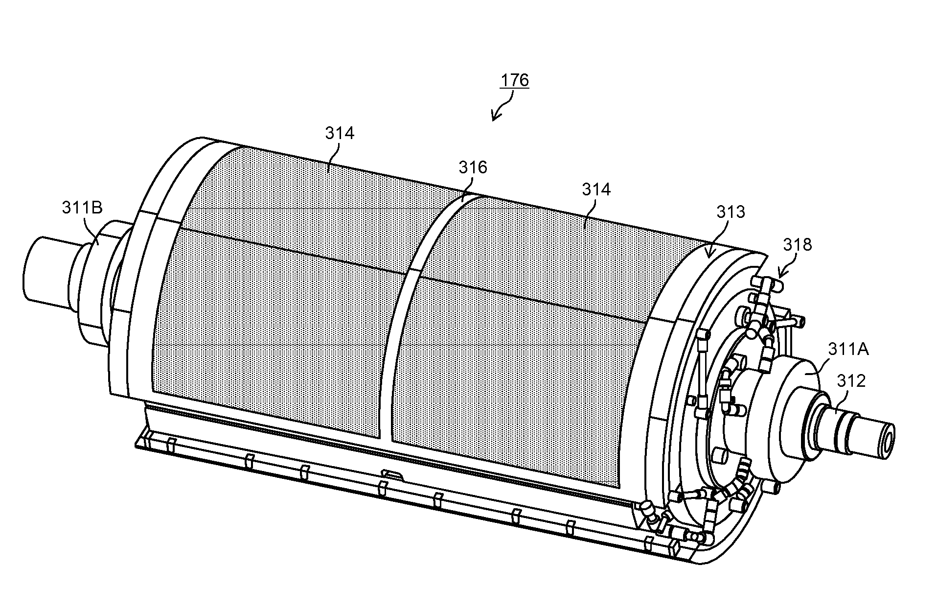
[0090]FIG. 6 is a general schematic drawing of an inkjet recording apparatus relating to a second embodiment of the present invention. This inkjet recording apparatus 100 is an inkjet recording apparatus using a pressure drum direct image formation method, which forms a desired color image by ejecting droplets of inks of a plurality of colors from inkjet heads 172M, 172K, 172C and 172Y onto a recording medium 22 (also called “paper” below for the sake of convenience) held on a pressure drum (image formation drum 170) of an image formation unit 116. The inkjet recording apparatus 100 is an image forming apparatus of an on-demand type employing a two-liquid reaction (aggregation) method in which an image is formed on a recording medium 22 by depositing a treatment liquid (here, an aggregating treatment liquid) on a recording medium 22 before ejecting droplets of ink, and causing the treatment liquid and ink liquid to react together. Elements of the composition and action which are sub...


PUM


Abstract

An inkjet recording apparatus includes: a conveyance device having a conveyance device surface with which a rear surface side of a recording medium comes into contact and which includes a plurality of suction holes for suctioning the recording medium with a negative pressure, and conveying the recording medium while changing suction locations of the recording medium suctioned via the suction holes; an inkjet head for ejecting ink onto the recording medium conveyed by the conveyance device in such a manner that an image is formed on the recording medium; and a control device which changes the suction locations of the recording medium suctioned via the suction holes, at a prescribed interval.

Description

BACKGROUND OF THE INVENTION[0001]1. Field of the Invention[0002]The present invention relates to an inkjet recording apparatus and an inkjet recording method, and more particularly, to an inkjet recording apparatus and an inkjet recording method whereby a recording medium can be conveyed by vacuum suction conveyance without creating suction marks in the recording medium.[0003]2. Description of the Related Art[0004]An inkjet recording apparatus which carries out recording by depositing ink droplets onto the recording surface of a recording medium is widely used in general applications as an image recording apparatus or an image forming apparatus, such as a printer, a facsimile device, a copying machine, or the like. In an inkjet recording method which uses a water-based ink, since ink droplets are ejected and deposited onto the recording medium, then a phenomenon known as cockling (a swelling deformation of the recording medium due to absorption in the recording medium) occurs due to...

Claims


Application Information

Patent Timeline
Patent Type & Authority Applications(United States)
IPC IPC(8): B41J29/38B41J2/01
CPCB41J2/155B41J2/175B41J2/17596B41J29/38B41J11/007B41J11/0085B41J11/002B41J11/0024B41J11/0022
Inventor HOUJOU, HIROAKI
Owner FUJIFILM CORP
Learn More