Method and apparatus for separating audio object

Inactive Publication Date: 2011-02-24
SAMSUNG ELECTRONICS CO LTD
View PDF9 Cites 23 Cited by
  • Summary
  • Abstract
  • Description
  • Claims
  • Application Information

AI Technical Summary

Benefits of technology

[0012]In the determining of a valid object, a difference value between a virtual source location at which sub-bands of a temporary object of a previous frame exist and a virtual source location at

Problems solved by technology

However, in a conventional audio object separation method, since the objects are separated from th

Method used


Image

  • Method and apparatus for separating audio object
  • Method and apparatus for separating audio object
  • Method and apparatus for separating audio object

Examples


Embodiment Construction

[0025]The attached drawings for illustrating exemplary embodiments of the present invention are referred to in order to gain a sufficient understanding of aspects of embodiments of the present invention. Hereinafter, aspects of exemplary embodiments of the present invention will be described in detail by explaining exemplary embodiments of the invention with reference to the attached drawings. Like reference numerals in the drawings denote like elements.

[0026]An encoding apparatus may generate a down-mixed audio signal by using a plurality of audio objects and may generate a bitstream by adding a space parameter to the down-mixed audio signal. The space parameter may include additional information such as a side information that may include virtual source location information.

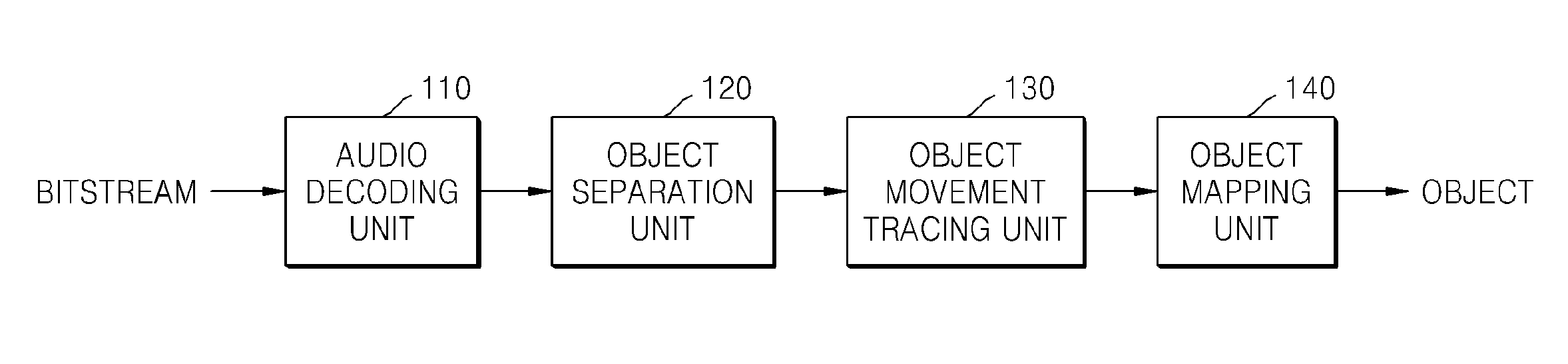
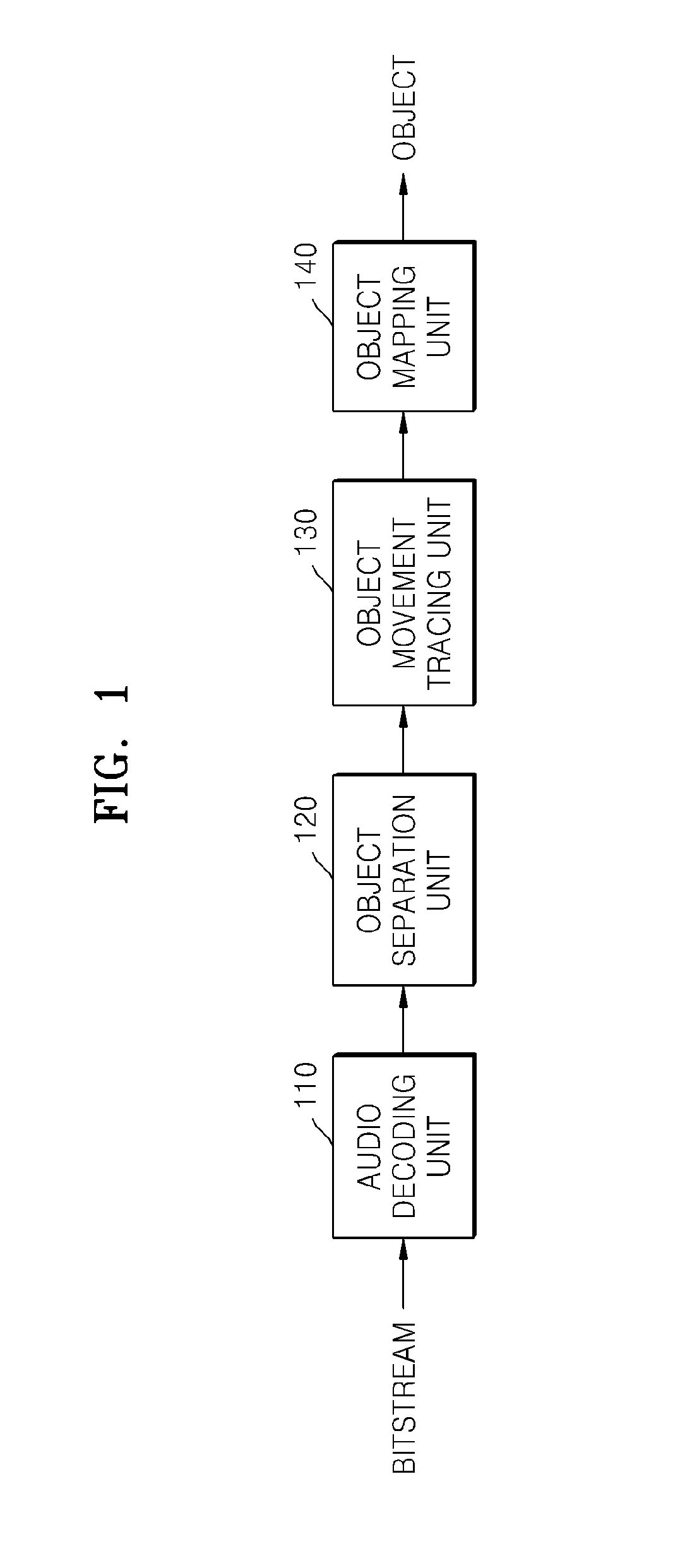
[0027]FIG. 1 is a block diagram of an exemplary apparatus for separating an audio object according to an exemplary embodiment of the present invention. Referring to FIG. 1, the apparatus for separating an audio...


PUM


Abstract

Provided is a method of separating an audio object that includes extracting virtual source location information and an audio signal from a bitstream, separating an object included in the audio signal based on a virtual source location, mapping objects of a previous frame and objects of a current frame located at the virtual source location, and extracting the mapped objects between continuous frames.

Description

CROSS-REFERENCE TO RELATED PATENT APPLICATIONS[0001]This application claims priority from Korean Patent Application No. 10-2009-0076337, filed Aug. 18, 2009, in the Korean Intellectual Property Office, the disclosure of which is incorporated herein in its entirety by reference.BACKGROUND[0002]1. Field[0003]Exemplary embodiments relate to a multichannel audio codec apparatus, and more particularly, to a method and apparatus for separating a meaningful object from an audio signal by using sound image location information.[0004]2. Description of the Related Art[0005]As home theater systems become popular, multichannel audio processing systems are being developed. Multichannel audio processing system may encode or decode a multichannel audio signal by using a side information, for example, space parameters.[0006]An audio encoding apparatus may down-mix a multichannel audio signal and encode a down-mixed audio signal by adding space parameters thereto. An audio decoding apparatus subsequ...

Claims


Application Information

Patent Timeline
IPC IPC(8): G06F17/00
CPCG10L19/008G10L21/0272G10L19/0204
Inventor KIM, HYUN-WOOKMOON, HAN-GIL
Owner SAMSUNG ELECTRONICS CO LTD
Why Eureka
Try Eureka