
Cord mounted jewelry plates

a technology of jewelry plates and cords, applied in the field of jewelry objects, can solve the problems of limiting the wearer's ability to modify, add or remove indicia or elements, and the components present a significant problem for the addition or removal of elements to the cords, and achieve the effect of preventing twisting and folding

Inactive Publication Date: 2011-03-03
MULLEN LAURA +1
View PDF5 Cites 30 Cited by
  • Summary
  • Abstract
  • Description
  • Claims
  • Application Information

AI Technical Summary

Benefits of technology

[0016]It is another object of the present invention to provide an article of jewelry that may have plates easily added to, or removed from, and elongated cord without impediment from the closing device of the cord.
[0018]It is a further object of the present invention to provide an article of jewelry wherein the size and shape of the mounting cord cooperates with the size and shape of access openings in personalized plates to provide a system wherein friction prevents the plates from moving relative to the cord.
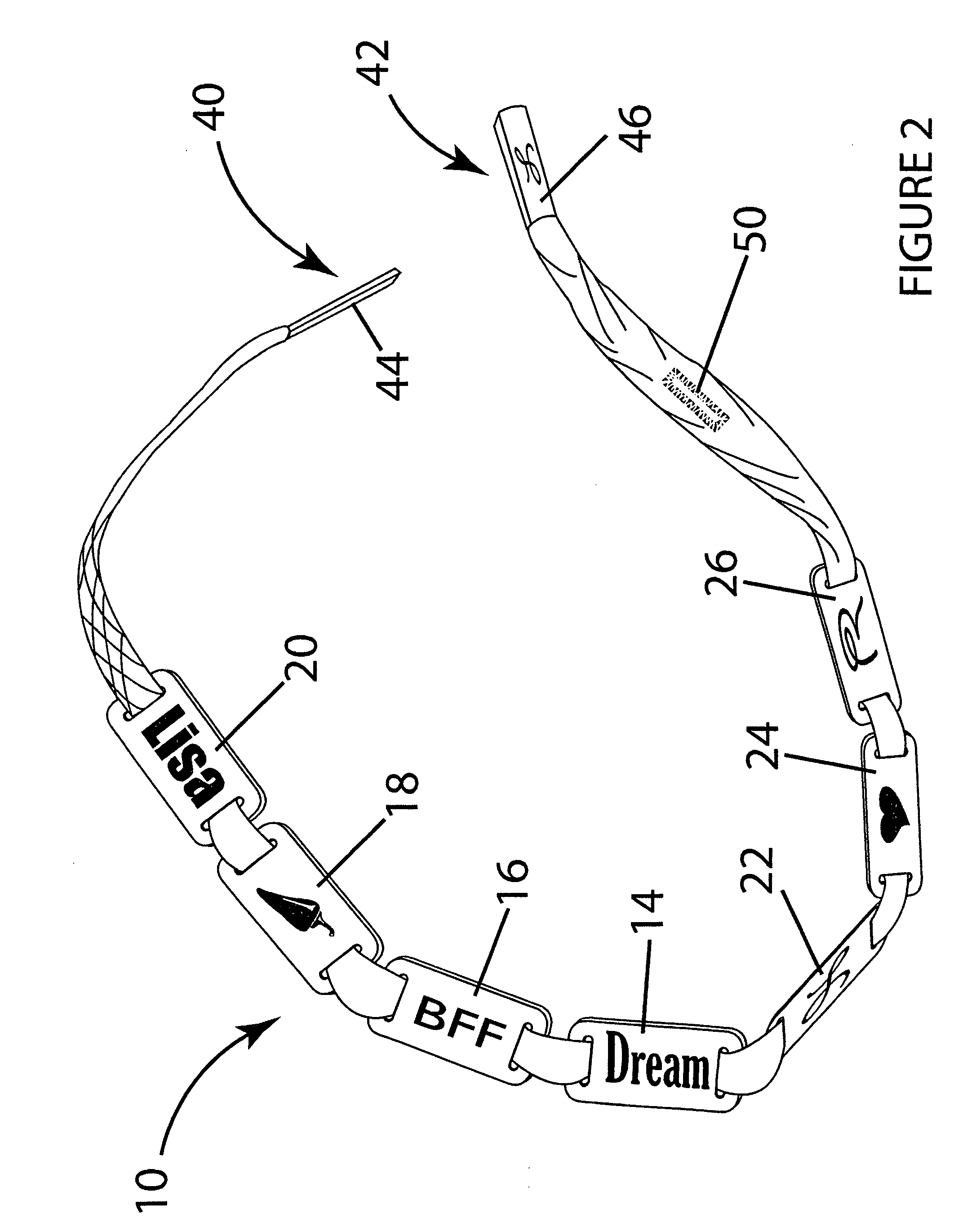
[0027]The elongated cord in the most preferred embodiment of the present invention comprises a generally flat cord having a generally rectangular cross section. This flat cord structure cooperates with the shape of the threading holes, which are rectangular and cooperatively sized for the generally flat cord to pass therethrough while preventing twisting and folding of said cord within the rectangular threading holes.

Problems solved by technology

First, the cost is high to create a personalized plate or arrangement of beads or charms if it is done in a permanent way, i.e. permanently affixed such as by soldering links of a chain, which limits the wearer's ability to modify, add or delete indicia or elements.
However, such interlocking clasp components present a significant problem for the addition or removal of elements to the cord if such personalized elements are to be slid onto the cord at the ends because of the size and shape of the clasp components.
The personalized elements added, changed or removed by a user have to be big enough or have provisions such that the closure clasps pass through them, which necessarily makes the personalized elements themselves large and bulky.
With prior art personalized jewelry, it was not possible to create such an individualized expression in a way that the separate elements were kept properly oriented and arranged.
However, such an arrangement suffers from the serious shortcoming that the charms are dangling and, necessarily free to twist and turn.
In addition, charms are generally not defined or designed by the wearer and, thus, lack much of personalization possible with the present invention.
For example, while it may be possible for a mother to display the names of her children if they have common names like Bill, Jane and Tom, if the children are more exotically named it will be impossible or very expensive to create a charm bracelet bearing their names.
Also, because the charms do not maintain a constant orientation or visibility, it will be very difficult for an onlooker to make out what the charm or what it represents and any desired perception of sequencing of the charms will be impossible.
The '172 patent does not, however, address the need to orient the bead axially on the strand.
In addition, the requirements in the '172 arrangement that each bead have a frictional inner diameter will greatly complicate the manufacturing of the beads.

Method used


Image

  • Cord mounted jewelry plates
  • Cord mounted jewelry plates
  • Cord mounted jewelry plates

Examples


Embodiment Construction

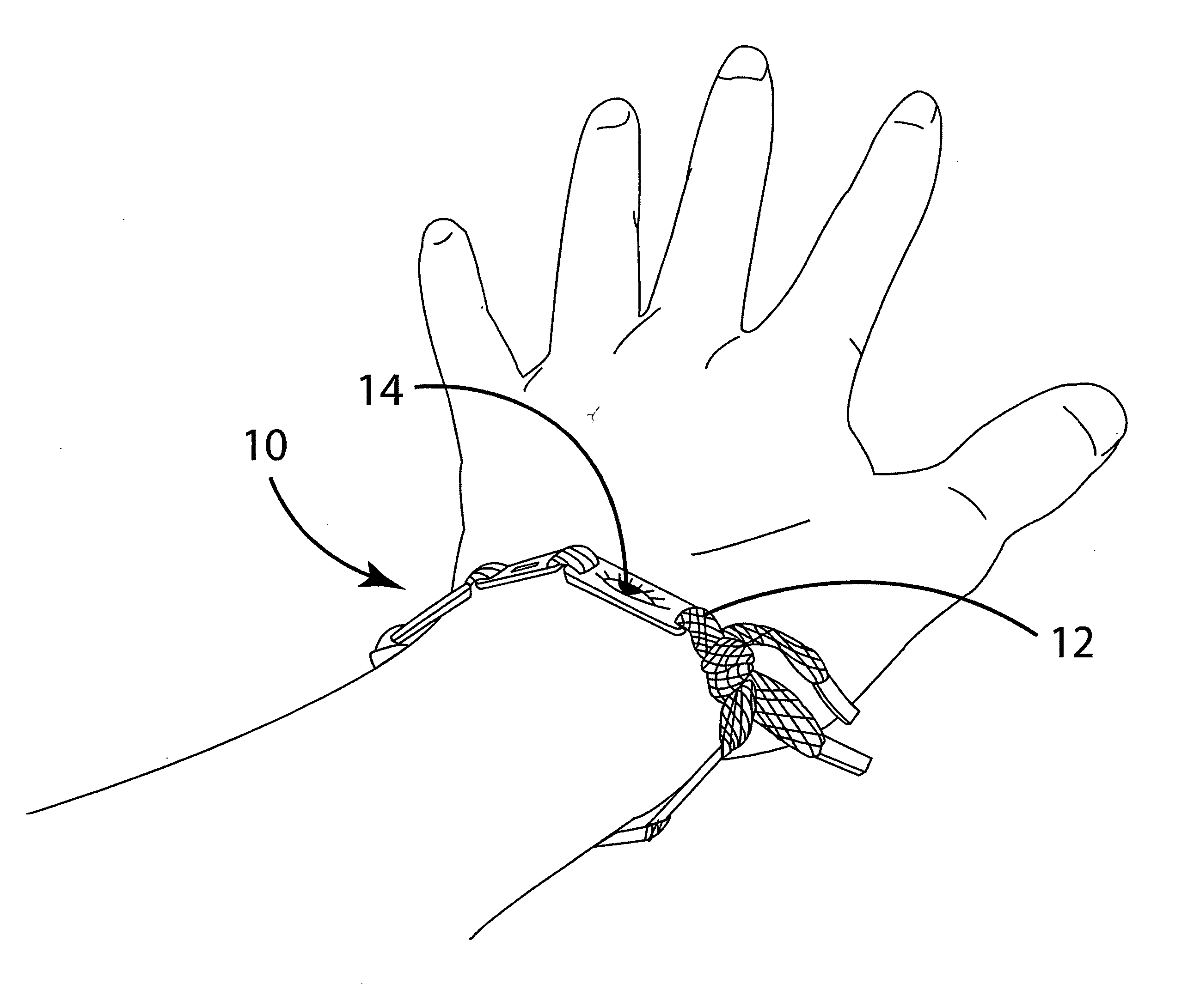
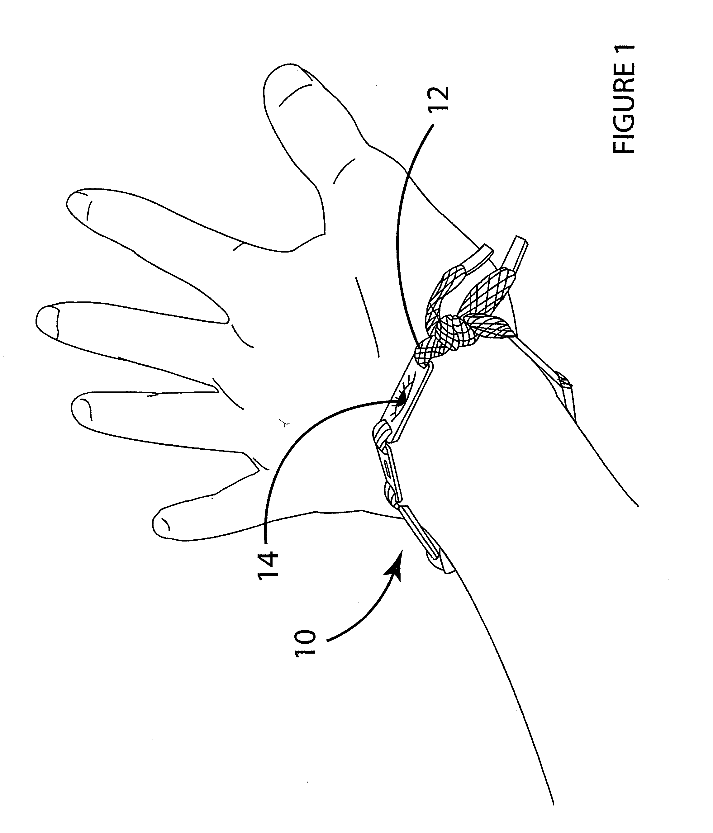
[0044]An article of jewelry 10 is provided that may be worn as a bracelet (see FIG. 1), although it may also be worn as a necklace or anklet without departing from the principles of the present invention.

[0045]The article of jewelry 10 comprises at least one plate 14 removably secured to an elongated mounting cord 12, as shown in FIG. 2. A series of plates 14, 16, 18, 20, 22, 24, 26 may be provided without departing from the principles of the present invention. The plates 14, 16, 18, 20, 22, 24, 26 may be personalized to display text, symbols, photos, logos, dates or any other indicia desired by the wearer and, in a significant feature of the present invention, may be arranged and oriented sequentially and maintained in the desired orientation and sequence. For example, in the event a wearer wishes to express a thought in a sentence, or to display the chronological names or photos of her children, each word of a sentence or name of photograph of a child may be represented on a singl...


PUM


Abstract

An article of jewelry comprising plates having indicia embossed or engraved thereon mounted on a shoelace type cord. The ends of the cord have rigid rectangular aglets and are threaded through rectangular holes at opposed ends of the plates. The generally flat cord cannot twist or fold within the rectangular holes in the plates so the plates always maintain the same orientation and position on the cord, allowing them to be arranged and displayed sequentially. The article of jewelry can be tied to itself using one hand because the cord is provided with a rectangular button hole of the same size as the rectangular holes in the plates. The rigid rectangular aglet is passed through the button hole, under the cord and back through the created loop and pulled tight, thereby tying the cord to itself using only one hand.

Description

FIELD OF THE INVENTION[0001]The present invention relates to an article of jewelry that may be personalized and modified by designing, adding or changing plates with individualized indicia thereon to a cord.BACKGROUND OF THE INVENTION[0002]This invention relates generally to jewelry and more particularly to jewelry that may be infinitely customized to suit an individual's tastes and interests. It has long been desirable to those wearing jewelry such as necklaces and bracelets to personalize such jewelry. Birthstones, charms, beads, plates or panels that are inscribed, printed or embossed, can represent names, birthdays, quotations, or other indicia like logos or other symbols that have particular meaning to the wearer. Jewelry can be and is customized in a vast number of ways to incorporate the individual tastes and interests of the wearer.[0003]Any article of jewelry that may be personalized suffers from a number of disadvantages. First, the cost is high to create a personalized pl...

Claims


Application Information

Patent Timeline
Patent Type & Authority Applications(United States)
IPC IPC(8): A44C5/18A44C5/00A44C25/00
CPCA43C9/02A44C5/18A44C5/025
Inventor MULLEN, LAURAJOHNSON, KELLY
Owner MULLEN LAURA
Learn More