Method and apparatus for manufacturing a helicopter rotor fairing, and a fairing obtained thereby

a technology of rotor fairing and manufacturing method, which is applied in the field of manufacturing a helicopter tail structure, can solve the problems of loss of composite materials, inability to completely reproduce the mechanical characteristics of parts in a series of parts of identical shapes, and general restriction of the technique to making parts of convex

Active Publication Date: 2006-08-03
EUROCOPTER
View PDF12 Cites 21 Cited by
  • Summary
  • Abstract
  • Description
  • Claims
  • Application Information

AI Technical Summary

Benefits of technology

[0044] This method makes it possible to avoid having recourse to two baking half-molds and passing through an autoclave. It requires tooling for holding the preforms so as to position the two preforms

Problems solved by technology

The operations of making the preform are generally performed manually, thereby leading to losses of composite material, and it does not enable the mechanical characteristics of the parts in a series of parts of identical shape to be made in completely reproducible manner.
Nevertheless, that technique is generally restricted to making parts of convex shape and presenting circular

Method used


Image

  • Method and apparatus for manufacturing a helicopter rotor fairing, and a fairing obtained thereby
  • Method and apparatus for manufacturing a helicopter rotor fairing, and a fairing obtained thereby
  • Method and apparatus for manufacturing a helicopter rotor fairing, and a fairing obtained thereby

Examples


Embodiment Construction

[0060] Unless specified to the contrary, in the present application, the terms “left” and “right” are used relative to an observer looking at the helicopter and / or helicopter tail structure from behind; the terms “front” and “rear” are used with reference to the normal forward travel direction of the helicopter.

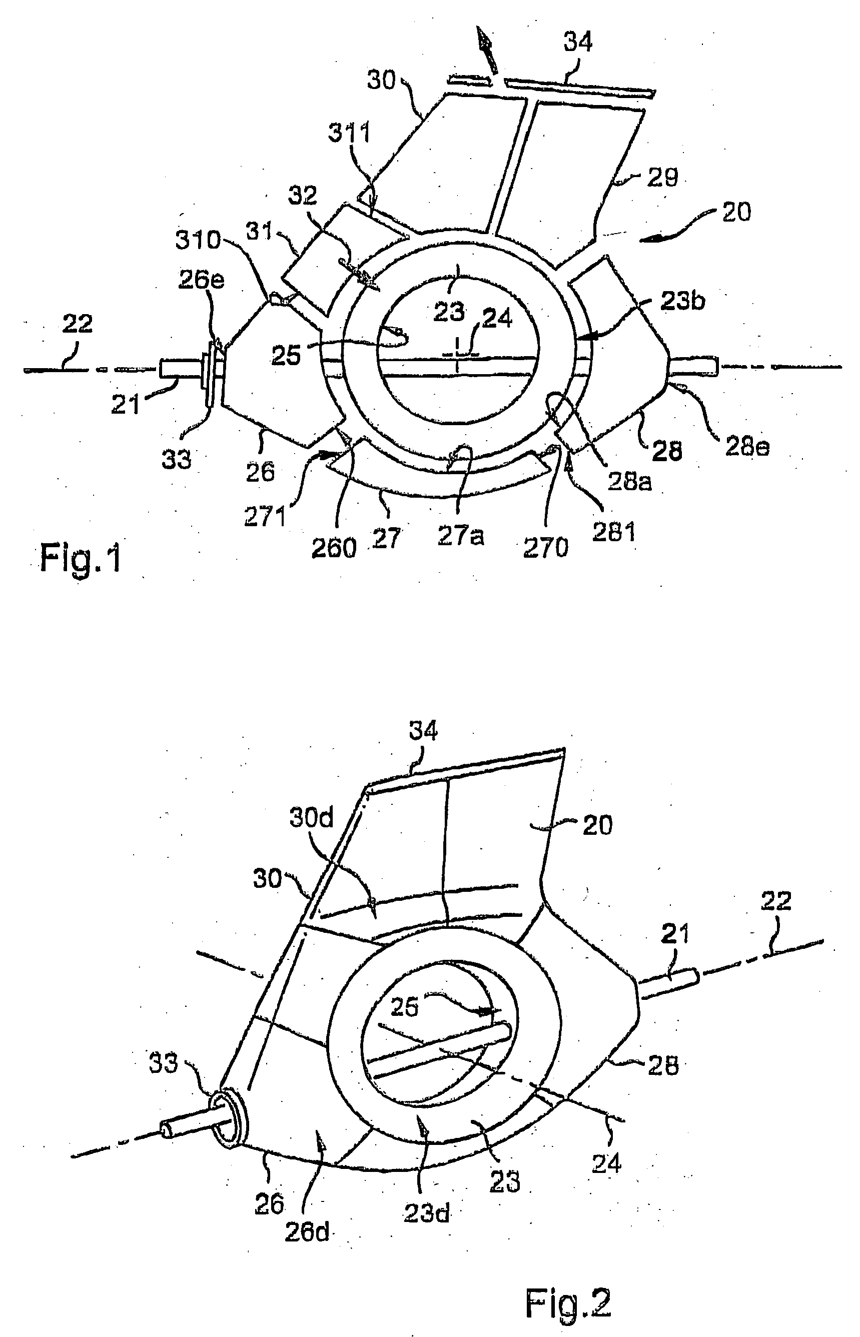
[0061] With reference to FIGS. 1 to 4 in particular, the apparatus for molding a composite fairing structure comprises a core or mandrel 20 suitable for being reversibly united with a shaft 21 presenting a longitudinal axis 22.

[0062] The mandrel comprises an annular central part 23 that is substantially circularly symmetrical about an axis 24; the part 23 is pierced by two orifices 25 in alignment, through which there extends the shaft 21.

[0063] With reference to FIG. 1, the mandrel further comprises six mandrel sectors or segments 26 to 31 that are disposed around the part 23 which they encircle.

[0064] For other implementations, the number of parts constituting the mandr...


PUM

PropertyMeasurementUnit
Timeaaaaaaaaaa
Massaaaaaaaaaa
Massaaaaaaaaaa

Abstract

The invention relates to a method of manufacturing a tail structure for a rotary wing aircraft, the structure comprising:
a tubular portion or duct (63) presenting two ends and including two collars or flanges (66, 70) extending respectively from each of said two ends; and
two curved fairing side walls (45, 47) extending respectively around the two collars or flanges; said two side walls being made of a composite material comprising an organic matrix and reinforcement; in a method of the invention, the side walls are united by solidifying the matrix.

Description

FIELD OF THE INVENTION [0001] The present invention relates to a method of manufacturing a fairing structure for an anti-torque rotor of a rotary wing aircraft—in particular a helicopter—, to apparatus or tooling for implementing the method, and also to structures obtained by the method. [0002] The technical field of the invention is that of manufacturing helicopters. [0003] The invention relates more particularly to manufacturing a helicopter tail structure that includes a faired anti-torque rotor. BACKGROUND OF THE INVENTION [0004] Patents U.S. Pat. No. 5,498,129 and FR 2 719 553 describe such a structure that is secured to the rear end of a tail boom extending the fuselage and that receives a rotor for opposing the torque exerted on the fuselage by the main rotor for providing the aircraft with lift and propulsion. [0005] That structure comprises an annular (or tubular) wall forming a duct defining a flow tunnel for the stream of air driven by the anti-torque rotor which is house...

Claims


Application Information

Patent Timeline
IPC IPC(8): B64C27/82
CPCB29C70/342B29L2031/08B29L2031/3088Y10T29/4932B64C2027/8254B64F5/0009Y10T29/49321B64C27/82B29C33/485B64F5/10
Inventor MAILLE, LAURENCEMOUTON, LUC
Owner EUROCOPTER
Why Eureka
Try Eureka