
Shade tarp as sun shield

Inactive Publication Date: 2005-04-05
WEBASTO VEHICLE SYST INT
View PDF22 Cites 18 Cited by
  • Summary
  • Abstract
  • Description
  • Claims
  • Application Information

AI Technical Summary

Benefits of technology

A primary object of the present invention is to improve a shade arrangement which is simple to operate and which has a simple structure for a motor vehicle, such that the formation of folds in the extended shade can be largely prevented.
A further object of the present invention is to improve a shade arrangement which has a side rail guide constructed to substantially prevent the formation of folds in the extended shade
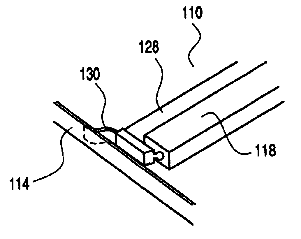
Alternatively, in accordance with the second object, it can also be provided that the opposing side edges of the shade tarp in a direction of its motion are guided laterally on guide rails and are held with pre-tensioning of the shade tarp in the transverse direction. These guide rails are suitable for guiding the shade tarp free of folds and without sagging even over a greater extension path. The shade tarp or shade tarp is movably fixed in the transverse direction in a transverse bow. Preferably, a free end of the shade tarp can be moved in the direction of the lengthwise extension of the transverse bow. This floating support of the shade tarp can equalize position differences during installation and the resulting formation of folds in the extended shade tarp can be prevented.
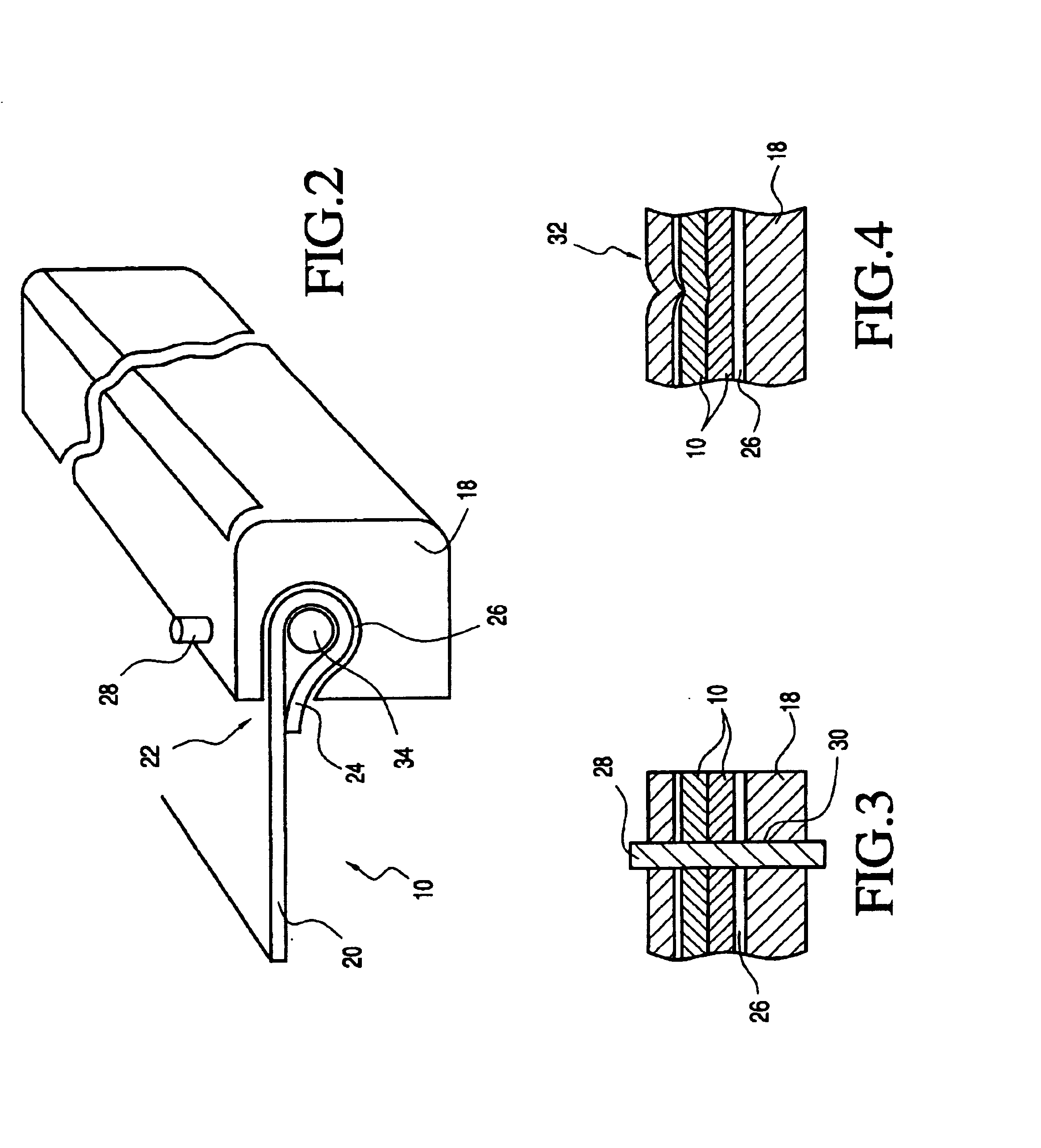
An embodiment of the invention calls for the free end of the shade tarp to be held in a groove of the transverse bow. Feasibly, the free end of the shade tarp with an additional stiffening holder element is pushed laterally into the groove. The stiffening holding element can be cemented and / or riveted to the shade tarp with its free end and in this way forms a stable counterpiece of the same width as the transverse bow, which counterpiece can be pushed a short distance relative to it. The floating support of the stiffening holding element in the transverse bow can equalize installation tolerances and prevent the formation of folds in the extended shade tarp.
Another embodiment of the invention calls for the opposing side edges of the shade tarp in a direction of its motion to be guided laterally on guide rails and to be held with pre-tensioning of the shade tarp in the transverse direction. These guide rails are suitable for guiding the shade tarp free of folds and without sagging over a greater extension path. According to one preferred embodiment, the holding element is centered by means of spring elements roughly in the middle between the guide rails. These spring elements can be made, for example, as leaf springs which face obliquely toward the guide rail, which are held on the holding part, and which provide for extensive centering of the holding part so that the formation of folds is prevented at the same time.

Problems solved by technology

In order to keep the shade tensioned at any time and to prevent the formation of folds, in this known arrangement, the construction cost is relatively great.
In general, when the known shade arrangements are installed the installation tolerances are often low and can lead to undesirable formation of folds in the extended sun-shielding shade.

Method used


Image

  • Shade tarp as sun shield
  • Shade tarp as sun shield
  • Shade tarp as sun shield

Examples


Embodiment Construction

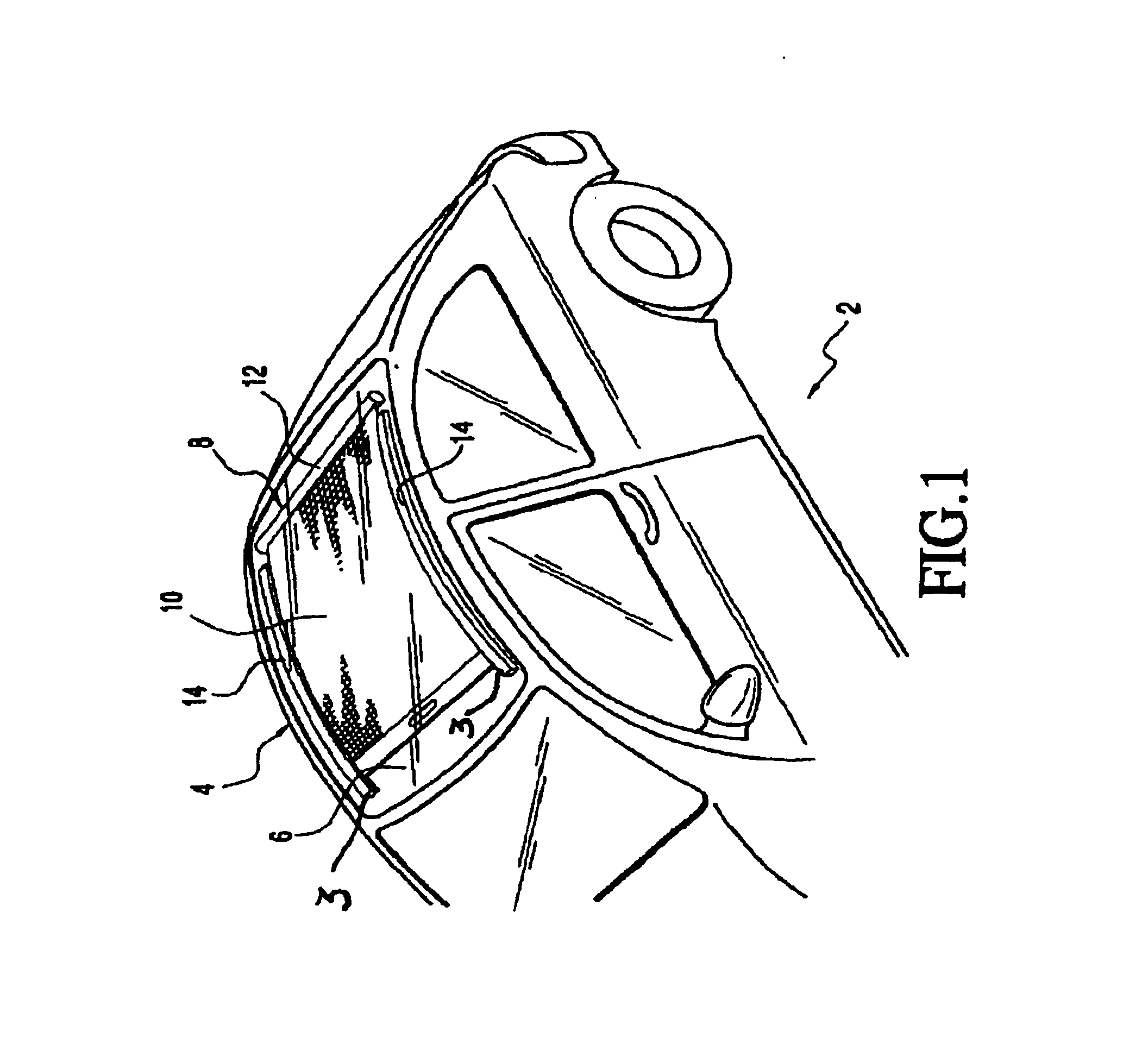
FIG. 1 Shows a motor vehicle 2 which has a motor vehicle roof 4 with a transparent roof section which, in this embodiment, is a fixed glass cover 6. The transparent roof section can also be a movable cover for closing or at least partially clearing the roof opening of a motor vehicle which is to be opened, for example, a sliding roof, sliding and lifting roof, spoiler roof or the like. Underneath the vehicle roof 4 or the glass cover 6, there is a sunshade 8 which has a shade tarp 10 and a take-up shaft 12 for winding and unwinding the shade tarp 10. The take-up shaft 12 contains a hollow cylindrical winding body 16 which is located on each end on a bearing part which is pivotally mounted on the vehicle roof via an axially projecting bearing journal. On a free end of the shade tarp 10, it is connected to a transverse bow 18 (compare FIG. 2) which in the closed position of the sunshade 8 can be fixed or hung in the end position underneath the roof. In addition, the shade tarp can be ...


PUM


Abstract

A sun shield which can be moved between an operating position under a translucent or transparent roof area of a motor vehicle roof (4) and a rest area next to this roof area, with a shade tarp (10) which is located underneath the roof (4) and which can be wound onto a take-up roller (12). A free end (22) of the shade tarp (10) is fixed in a transverse bow (18, 118) with pre-tensioning in the transverse direction in the transverse bow (18). Fixing of the free end (22) of the shade tarp (10) in the transverse bow (18, 118) is preferably via insertion of a turn-down portion of the free end of the tarp (10) into a groove of the transverse bow (18, 118) where it is held by pins or clamping elements formed by plastic deformation of areas of the transverse bow (18, 118).

Description

BACKGROUND OF THE INVENTION1. Field of the InventionThe invention relates to a sun shield which can be moved between an operating position under a translucent roof area and a rest position next to this roof area, especially for an at least partially transparent motor vehicle roof with a shade tarp which is located underneath the roof and which is wound onto a take-up roller.2. Description of Related ArtShades of the initially mentioned type are used as anti-glare devices or to cover glass surfaces in a motor vehicle in various configurations. Thus, for example, published German Patent Application DE 42 10 972 A1 describes a shade as an anti-glare device with a pivotally mounted take-up roller for a roll-up hanging with a fall rod located on its pull out-side end, and with a drive device for the take-up roller. The hanging is guided when at least one telescoping rod is extended and engages the fall rod of the hanging. Such a shade is especially suited for the rear window of a motor v...

Claims


Application Information

Patent Timeline
IPC IPC(8): B60J1/20B60J7/00
CPCB60J1/2044B60J7/0015B60J1/2052
Inventor ENGL, ANDREASGUVEN, ATTILA
Owner WEBASTO VEHICLE SYST INT
Learn More