
Grip

Active Publication Date: 2011-03-03
KUBOTA LTD
View PDF24 Cites 22 Cited by
  • Summary
  • Abstract
  • Description
  • Claims
  • Application Information

AI Technical Summary

Benefits of technology

[0004]The present invention has been made having regard to the above-noted drawbacks of the conventional art, and its object is to provide a grip having good operability.
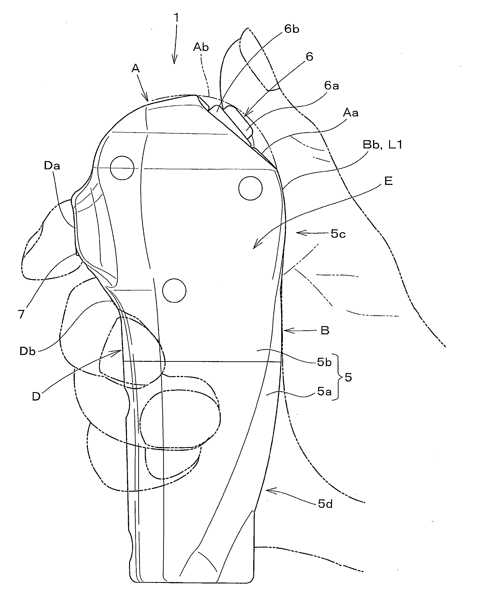
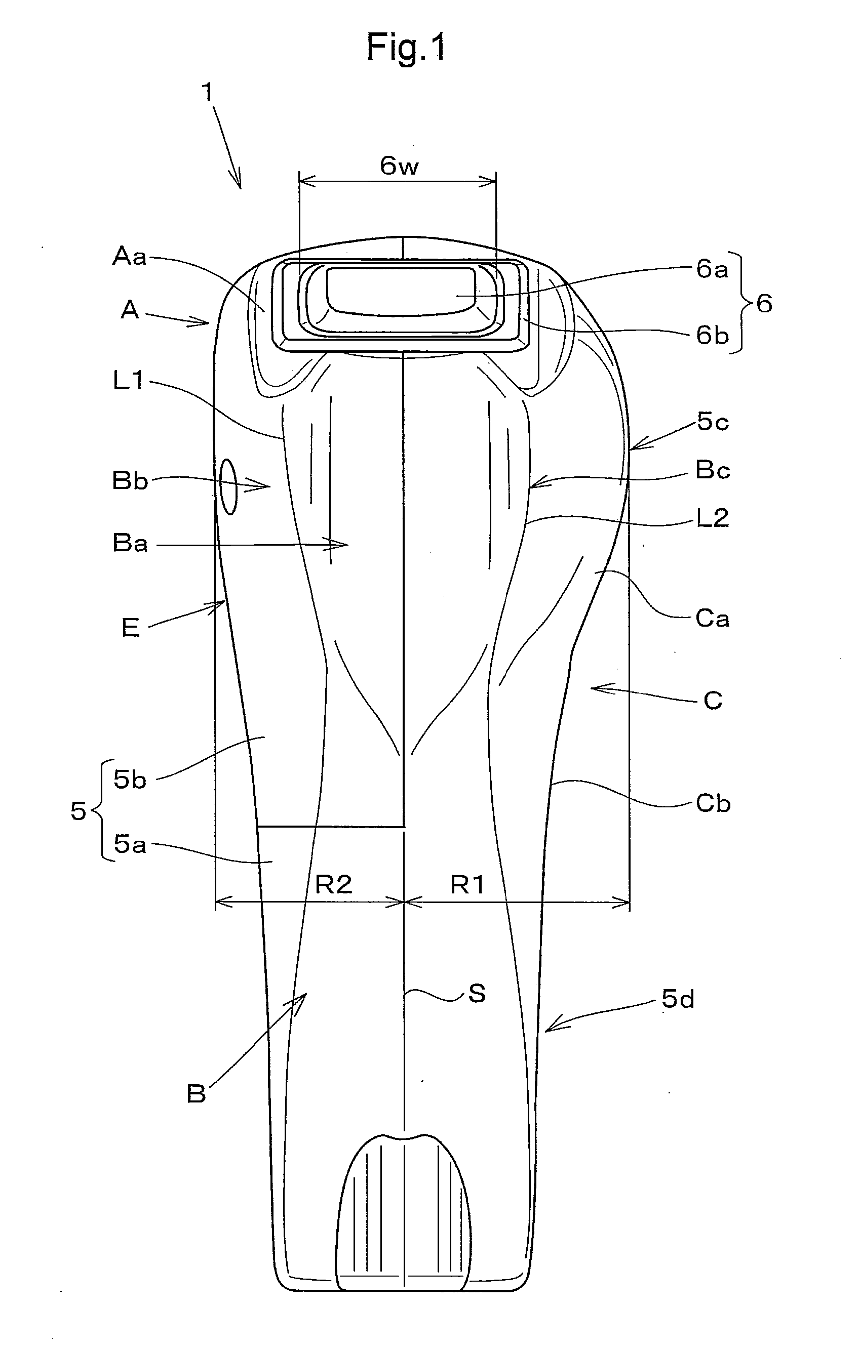
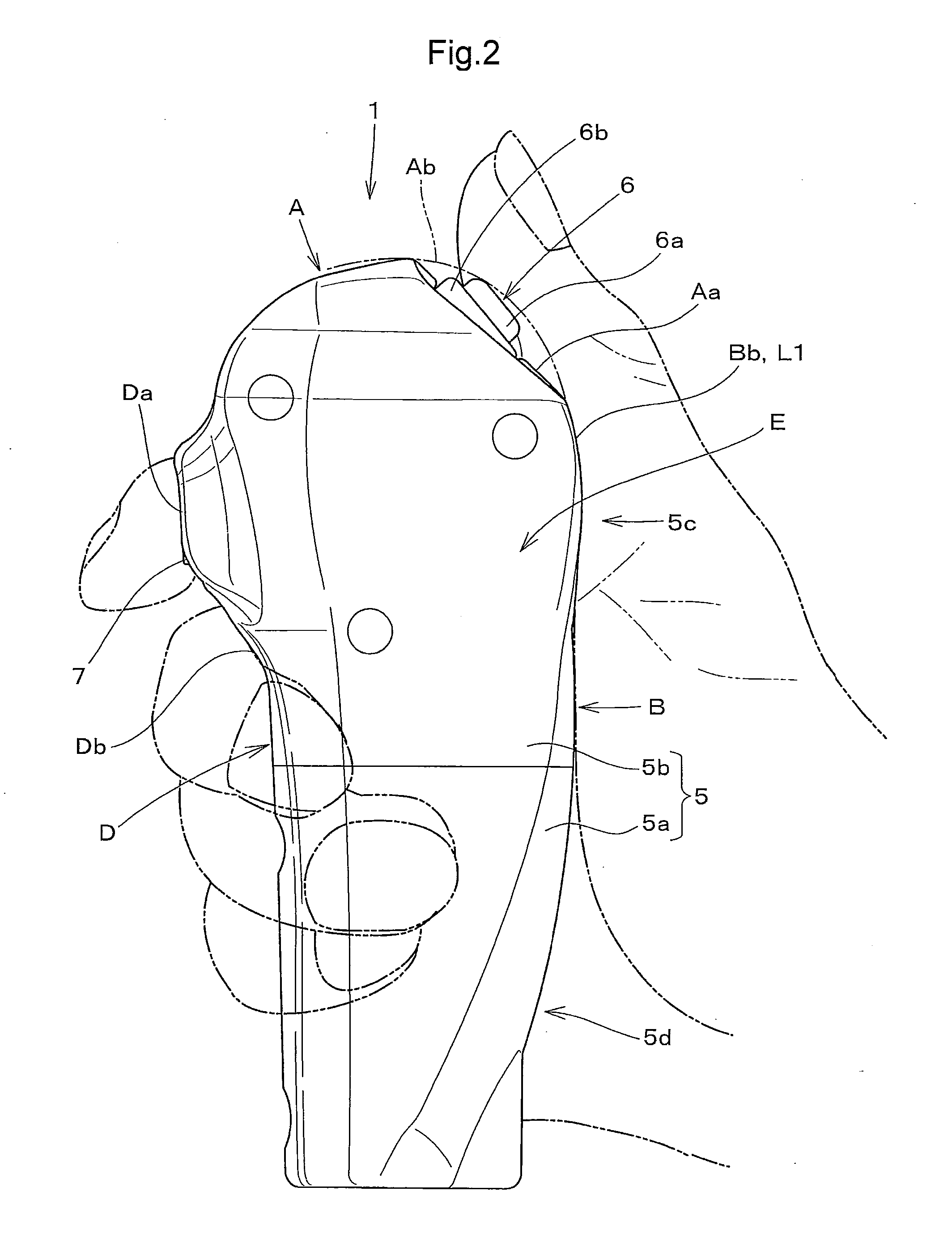
[0021]According to the present invention, it is possible to prevent the switch from being erroneously operated by guiding the thumb with the inside of the first joint of the thumb being placed along the upper part of the ball-receiving surface of the grip body, and by applying resistance against the operator's hand that is about to advance into the switch.

Problems solved by technology

In addition, the thumb may advance into the switch inadvertently (or violate a border of a switching operational range) or the operator's palm may cover the top portion of the grip body to advance into the side of the switch when the grip is held.
This does not necessarily provide good operability.

Method used


Image

  • Grip
  • Grip
  • Grip

Examples


Embodiment Construction

[0032]The present invention will be described hereinafter in reference to the accompanying drawings.

[0033]FIG. 10 shows a driver's section of a backhoe as an example of industrial machines. The driver's section includes a driver's seat 11, a manually operable device (control lever) 2 provided in a forward right side part of the driver's seat 11 for actuating a blade of a dozer apparatus, and a grip 1 mounted on the manually operable device 2 to form a gripping control portion 3.

[0034]The manually operable device 2 including the grip 1 attached to an upper end of a lever rod 2a is adapted to move the blade of the dozer apparatus vertically by being pivotally operated in a fore-and-aft direction, to change the angle of the blade (to allow the blade to move back and forth at the right or left side thereof) by pressing a switch provided at a top portion of the grip with the operator's thumb, and to switch a traveling speed of the backhoe between “high” and “low” by pressing a push butto...


PUM


Abstract

A grip comprises a grip body forming a gripping control portion of a manually operable device to be held with the operator's palm and fingers. The grip body includes a ball-receiving surface coming into contact with the ball of the thumb, a palm-receiving surface coming into contact with a middle portion of the palm and the ball of the little finger, a finger-receiving surface coming into contact with the fingers, an open surface positioned between the tips of the fingers and the ball of the thumb for receiving the thumb when the grip body is held, and a switch mounted on a top portion of the grip body to be operable with the thumb. The grip body further comprises a thumb-guiding portion in the form of a shallow groove formed at an upper part of the ball-receiving surface of the grip body, the inside of the first joint of the thumb being placed along the thumb-guiding portion when the switch is operated, and a rising portion formed on at least either one of portions between the thumb-guiding surface and the open surface and between the thumb-guiding surface and the palm-receiving surface for applying resistance when the operator's hand advances into the switch.

Description

TECHNICAL FIELD OF THE INVENTION[0001]The present invention relates to a grip forming a gripping control portion of a manually operable device of an industrial machine.BACKGROUND ART[0002]An example of a grip forming a gripping control portion of a manually operable device of an industrial machine is disclosed in Japanese Unexamined Patent Application Publication No. 2008-293899. More particularly, the grip comprises a grip body that is held with the operator's palm and fingers, a switch mounted on a top portion of the grip body to be operable with the thumb, and a push button provided in a front upper portion of the grip body to be operable with the operator's first finger or second finger, the grip body including a ball-receiving surface coming into contact with the ball of the thumb, a palm-receiving surface coming into contact with a middle portion of the palm and the ball of the little finger, a finger-receiving surface coming into contact with the fingers, and an open surface ...

Claims


Application Information

Patent Timeline
IPC IPC(8): G05G1/06
CPCG05G1/06Y10T74/20612G05G2009/04774
Inventor MIURA, KEISUKEUEDA, MASAAKIUOTANI, IKUHIROKOHNO, KENJISAKAI, TAKEHIRO
Owner KUBOTA LTD
Learn More