Dual Mode End Effector

a technology of end effector and dual-mode, which is applied in the direction of wheel mounting apparatus, instruments, manufacturing tools, etc., can solve the problems that conventional methods that conduct such steps require a significant capital investment and human oversigh

Active Publication Date: 2011-03-03
ANDROID INDS OF MICHIGAN
View PDF23 Cites 24 Cited by
  • Summary
  • Abstract
  • Description
  • Claims
  • Application Information

AI Technical Summary

Problems solved by technology

Usually, conventional methodologies that conduct such steps require a significant capital investment and human oversight.

Method used


Image

  • Dual Mode End Effector
  • Dual Mode End Effector
  • Dual Mode End Effector

Examples


Embodiment Construction

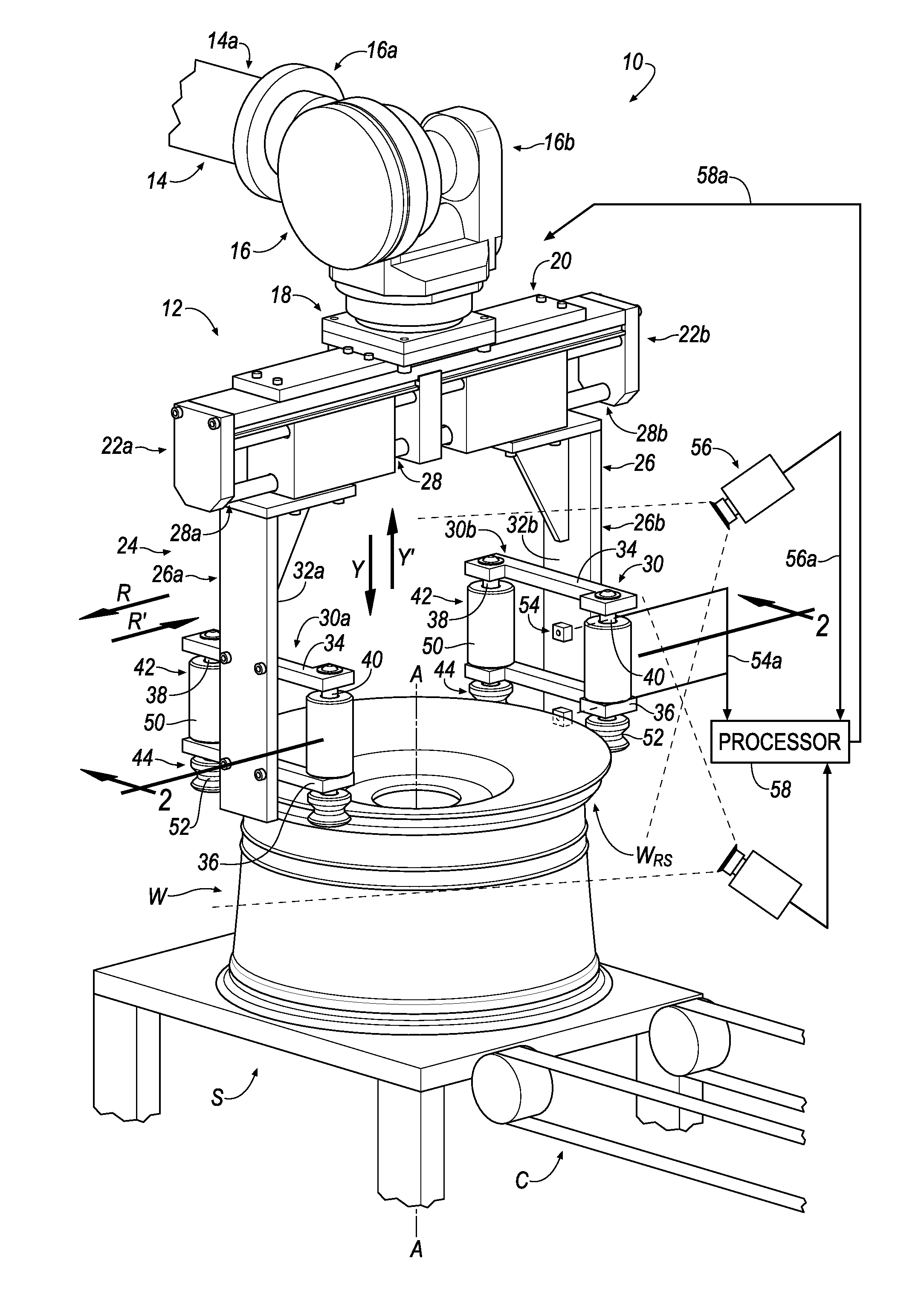
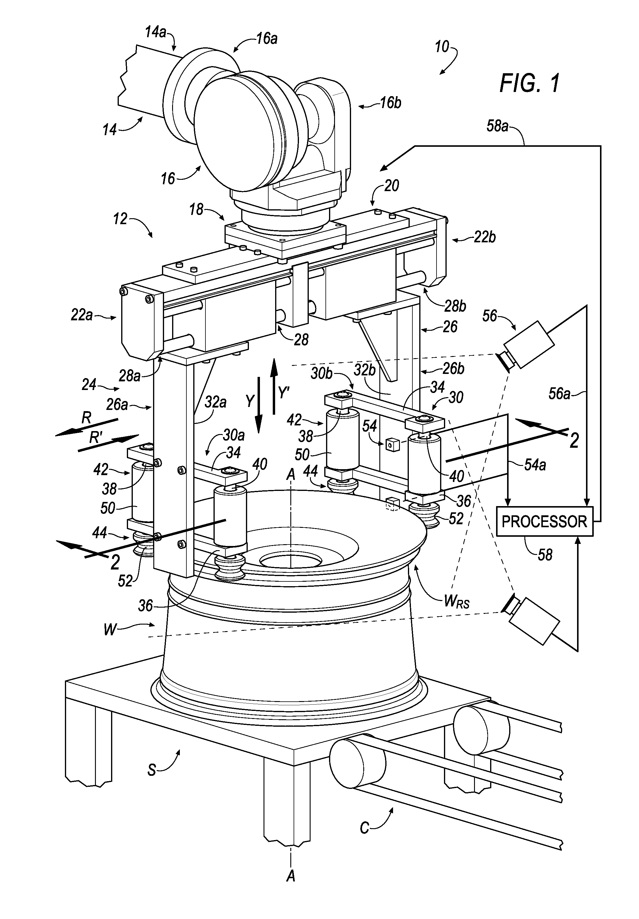
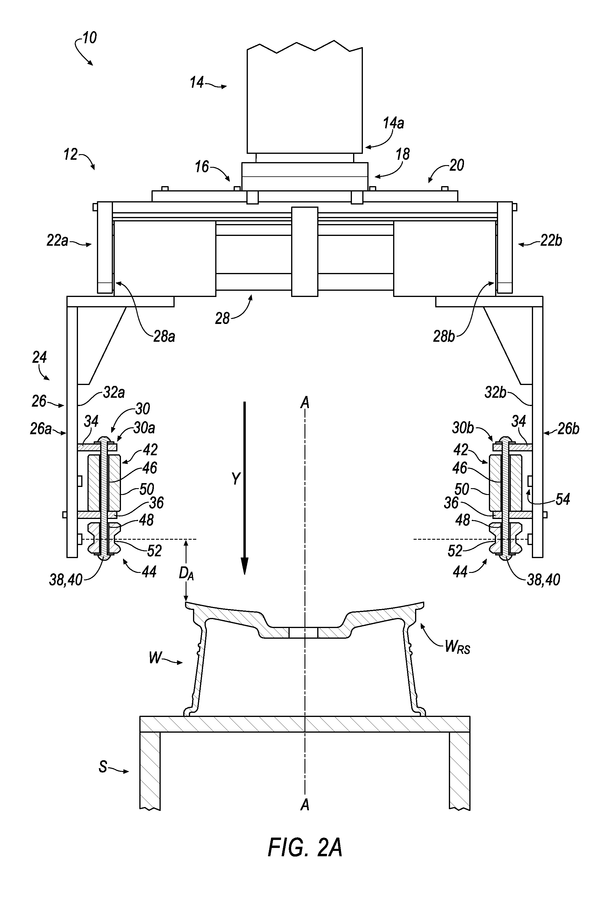
[0015]The Figures illustrate an exemplary embodiment of an apparatus that is utilized during the process for manufacturing a tire-wheel assembly in accordance with an embodiment of the invention. Based on the foregoing, it is to be generally understood that the nomenclature used herein is simply for convenience and the terms used to describe the invention should be given the broadest meaning by one of ordinary skill in the art.

[0016]In an embodiment, an apparatus is shown generally at 10 in FIGS. 1-4D. The apparatus 10 may or may not interface with a “single-cell” workstation. In the forgoing disclosure, it will be appreciated that term “single-cell” indicates that the workstation provides a tire-wheel assembly (not shown) without requiring a plurality of successive, discrete workstations that may otherwise be arranged in a conventional assembly line. Rather, the single cell workstation provides one workstation having a plurality of subs-stations (not shown), each performing a speci...


PUM


Abstract

A dual mode end effector is disclosed. The dual mode end effector includes a bridge member having a first end and a second end, wherein the bridge member includes a first substantially axial flange extending from the first and, wherein the bridge member includes a second substantially axial flange extending from the second end; a tire/wheel gripping assembly connected to the bridge member, wherein the tire/wheel gripping assembly includes a pair of substantially axial members, a substantially radial support member, and a pair of radially-projecting engaging assemblies, wherein the pair of substantially axial members are movably-supported upon the substantially radial support member, wherein a first end of the substantially radial support member is connected to the first substantially axial flange of the bridge member, wherein the a second end of the substantially radial support member is connected to the second substantially axial flange of the bridge member, wherein a first radially-projecting engaging assembly of the pair of radially-projecting engaging assemblies is connected to an inner radial surface of a first substantially axial member of the pair of substantially axial members, wherein a second radially-projecting engaging assembly of the pair of radially-projecting engaging assemblies is connected to an inner radial surface of a second substantially axial member of the pair of substantially axial members.

Description

RELATED APPLICATION[0001]This disclosure claims priority to U.S. Provisional Patent Application Ser. No. 61 / 237,093 filed on Aug. 26, 2009.FIELD OF THE INVENTION[0002]The disclosure relates to an apparatus that is utilized during the process for manufacturing a tire-wheel assembly and to an apparatus having a manipulatable orientation that may be selectively modified to permit engagement of the apparatus with one of a tire or a wheel.DESCRIPTION OF THE RELATED ART[0003]It is known in the art that a tire-wheel assembly is assembled in several steps. Usually, conventional methodologies that conduct such steps require a significant capital investment and human oversight. The present invention overcomes drawbacks associated with the prior art by setting forth a simple system and method for assembling a tire-wheel assembly.BRIEF DESCRIPTION OF THE DRAWINGS[0004]The disclosure will now be described, by way of example, with reference to the accompanying drawings, in which:[0005]FIG. 1 is a...

Claims


Application Information

Patent Timeline
Patent Type & Authority Applications(United States)
IPC IPC(8): B60C25/132
CPCB25J15/0028B60C25/0515B60C25/05B25J15/0253
Inventor LAWSON, LAWRENCE J.LARSON, DAVID H.
Owner ANDROID INDS OF MICHIGAN
Why Eureka
Try Eureka