Sealing structure using a liquid gasket

a sealing structure and liquid gasket technology, applied in the direction of gear seals, gear lubrication/cooling, engine seals, etc., can solve the problems of reducing the sealing performance, and requiring more time for curing, so as to achieve sufficient sealing performance, secure sufficient sealing performance, and save space

Active Publication Date: 2011-03-03
TOYOTA JIDOSHA KK
View PDF2 Cites 10 Cited by
  • Summary
  • Abstract
  • Description
  • Claims
  • Application Information

AI Technical Summary

Benefits of technology

[0017]Preferably, the first member and the second member form a case of a power transmitting device for vehicles, and the flow of the oil is an oil flow generated in the case by the rotation of a specific gear in the case forming the power transmitting device for vehicles. As a result, in a case of a power transmitting device for vehicles, a gasket lump portion for positively making contact with air or oil is formed so as to accelerate curing, and, without hermetically sealing the boundary portion (interface portion) between the liquid gasket and each member, the entry of oil into the boundary portion due to the oil flow in the case generated by the rotation of a specific gear is minimized. Accordingly, for example, when the liquid gasket has not sufficiently cured in a completion test of a power transmitting device for vehicles, the entry of oil into the boundary portion due to the oil flow is minimized, securing sufficient sealing performance. Further, for example, also after the liquid gasket sufficiently cures, the entry of oil into the boundary portion due to the oil flow is minimized, maintaining the sufficient sealing performance. Moreover, because a hermetically sealed state is not formed, an air layer for accelerating the curing of a liquid gasket is not required. Accordingly, for example, disposition of the liquid gasket at the bottom of the case, where oil constantly collects, is also possible. In addition, there is no need to provide a space for forming a hermetically sealed state, and accordingly, a smaller power transmitting device for vehicles is possible, whereby space saving is also achieved.
[0018]The object indicated above may be achieved according to a second mode of the invention, which provides (a) a sealing structure using a liquid gasket, having a liquid gasket interposed in the form of a thin film between mating surfaces of a first member and a second member, thereby preventing the movement of oil via the mating surfaces, the sealing structure includes (b) an oil-shielding portion that covers a boundary portion where the liquid gasket and the first member come into contact, thereby preventing an oil flow from directly striking the boundary portion, and is provided on an oil-flow upstream side from the boundary portion.
[0019]According to the second mode of the invention, the oil-shielding portion that covers the boundary portion where the liquid gasket and the first member come into contact, thereby preventing the oil flow from directly striking the boundary portion, and is provided on the oil-flow upstream side from the boundary portion. This therefore provides a sealing structure using a liquid gasket, in which without hermetically sealing the boundary portion (interface portion) between the liquid gasket and each member, the entry of oil into the boundary portion due to the oil flow is minimized. Accordingly, for example, when the liquid gasket has not sufficiently cured, the entry of oil into the boundary portion due to the oil flow is minimized, securing sufficient sealing performance. Further, for example, also after the liquid gasket sufficiently has cured, the entry of oil into the boundary portion due to the oil flow is minimized, maintaining the sufficient sealing performance. Moreover, because a hermetically sealed state is not formed, an air layer for accelerating the curing of a liquid gasket is not required. Accordingly, for example, disposition of the liquid gasket at the bottom, where oil constantly collects, is also possible. In addition, there is no need to provide a space for forming a hermetically sealed state, so space saving is also achieved.

Problems solved by technology

This possibly allows the oil to enter into the interface 8, reducing the sealing performance.
As a result, subsequent adhesion of the liquid gasket 5 thereto will be difficult, causing remarkable reduction in sealing performance.
However, by the property of the liquid gasket 5, the hermetically sealed state results in more time required to complete curing.
In such a case, desired sealing performance cannot be obtained.
However, due to the structural or space limitations on the case or the like, it is sometimes impossible to crease a hermetically sealed state or to provide an air layer.
Further, when the mating surfaces of members, where a problem often occurs, are located in a lower part of the case (for example, a place where oil collects), providing of an air layer may be impossible.

Method used


Image

  • Sealing structure using a liquid gasket
  • Sealing structure using a liquid gasket
  • Sealing structure using a liquid gasket

Examples


first embodiment

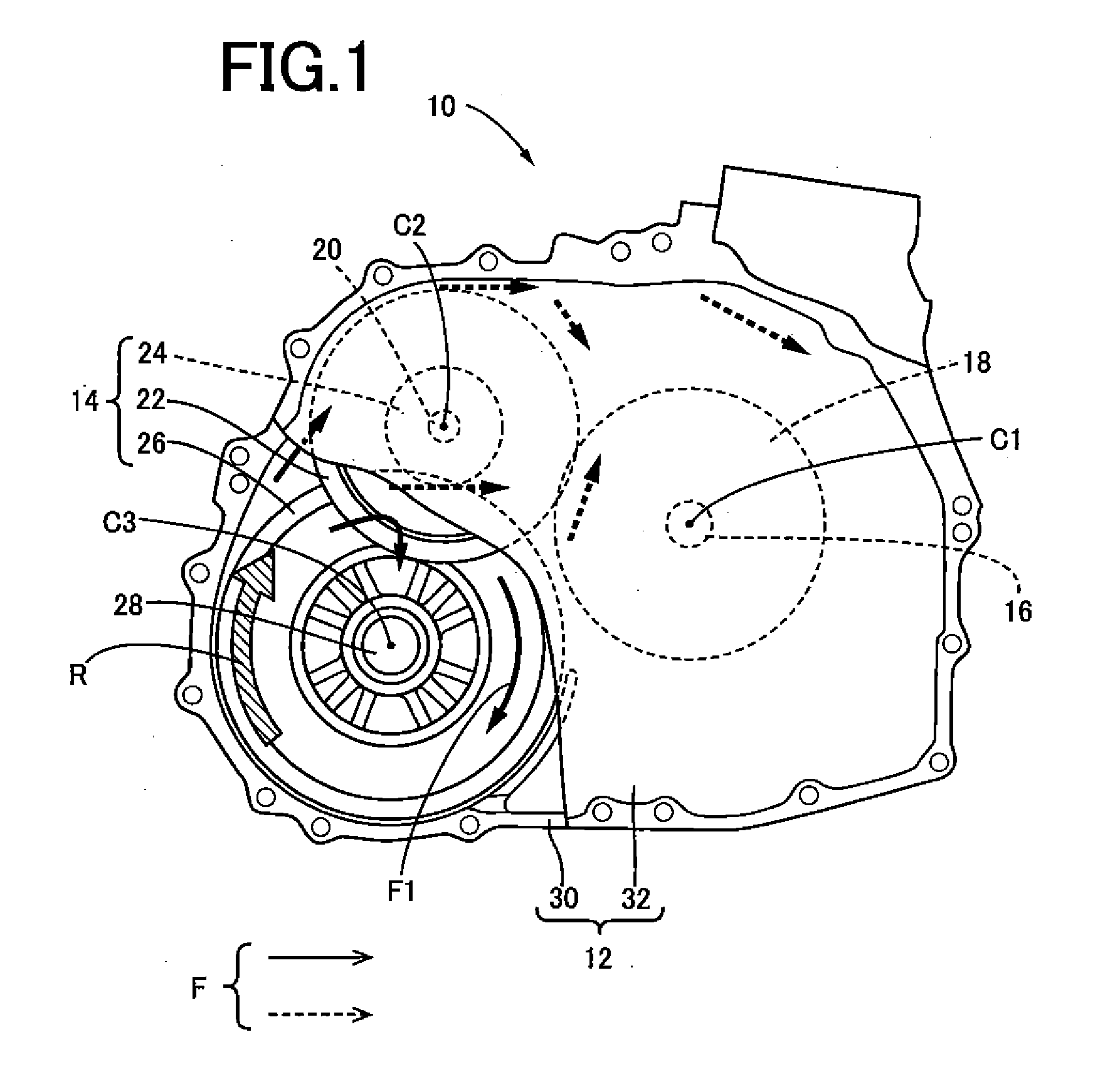
[0032]A power transmitting device 10 for vehicles comprises a non-illustrated automatic transmission, a reduction mechanism portion 14, a non-illustrated differential mechanism portion, and the like that are installed in a transaxle case 12 (hereinafter referred to as a case 12) that serves as a nonrotational element attached to the vehicle body, for example. The power transmitting device 10 for vehicles is a transaxle that is suitable for use in FF vehicles, in which the device is mounted in the left-right direction of the vehicle (transversely mounted). The automatic transmission is installed, for example, on a first shaft 16 having a first axis C1, which serves as a main shaft that is connected to a non-illustrated drive power source in a power transmissible manner. The automatic transmission changes the speed of the rotation of the first shaft 16, and outputs it from an output gear 18 installed on the first shaft 16. The output gear 18 functions as a counter drive gear that mesh...

second embodiment

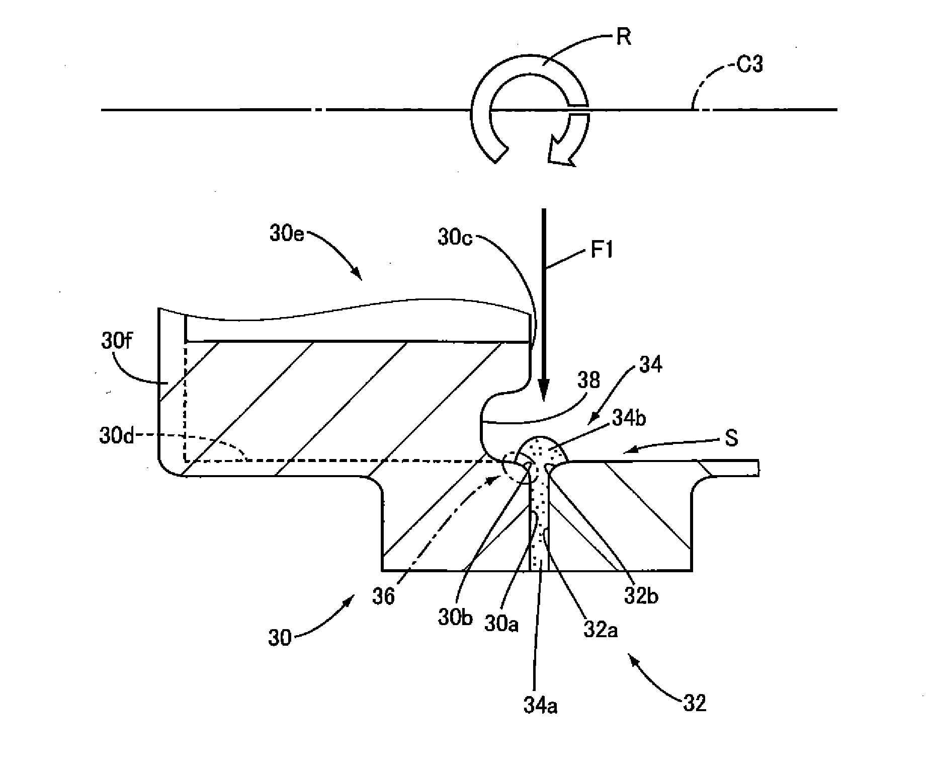
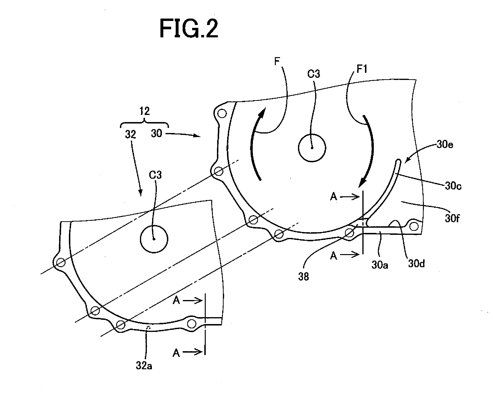
[0042]In the above embodiment, a slot 38 was formed at the portion where the rib 30e is formed in the case body 30. The slot 38 prevents the mating surface 30a and the protruding surface 30c of the case body 30 from forming one continuous surface, so that the interface between the gasket lump portion 34b and the protruding surface 30c is not substantially parallel to the oil flow F1, and a strong oil flow F1 does not directly hit the interface. Incidentally, as shown in FIG. 9A, for example, also at a portion where the rib 30e is not formed, there is a possibility that the entry of oil due to the oil flow F into the interface between the gasket lump portion 34b and each member (the case body 30 and the case cover 32) may not be sufficiently eliminated. The present embodiment thus proposes an oil-shielding portion for a case where rib 30e is not formed.

[0043]In FIGS. 4 and 5, the oil-shielding portion of the present embodiment is a first direct-hit-avoiding plate 40 having a roof-lik...

third embodiment

[0048]The present embodiment further proposes other oil-shielding portion that corresponds to a portion where no rib 30e is formed, which is different from the second embodiment.

[0049]FIG. 7 shows other embodiment which differs from that of FIG. 5. In FIG. 7, the oil-shielding portion of the present embodiment corresponds a first protruding portion 46 having a roof-like shape to cover the gasket lump portion 34b. The first protruding portion 46 is formed on the wall surface 30d of the case body 30, which intersects the mating surface 30a of the case body 30. Specifically, the first protruding portion 46 is provided at a location other than in the vicinity of the gasket lump portion 34b, and has a protruding wall portion 46a and a plate-like roof portion 46b. The protruding wall portion 46a is formed to have predetermined thickness to extend toward the inside of the case 12 in the direction perpendicular to the wall surface 30d, and the roof portion 46b is formed to perpendicularly e...


PUM


Abstract

A sealing structure using a liquid gasket, having a liquid gasket interposed in the form of a thin film between mating surfaces of a first member and a second member, thereby preventing the movement of oil via the mating surfaces, the sealing structure, includes at oil-side end portions of the mating surfaces, a gasket lump portion that is formed of an excess of the thin-film liquid gasket squeezed out from the mating surfaces, and an oil-shielding portion that covers a boundary portion where the gasket lump portion and the first member come into contact, thereby preventing a flow of the oil from directly striking the boundary portion, and is provided on an oil-flow upstream side from the boundary portion.

Description

[0001]The disclosure of Japanese Patent Application No. 2009-194808 filed on Aug. 25, 2009 including the specification, drawings and abstract is incorporated herein by reference in its entirety.BACKGROUND OF THE INVENTION[0002]1. Technical Field[0003]The present invention relates to a sealing structure using a liquid gasket that is interposed in the form of a thin film between the mating surfaces of a first member and a second member.[0004]2. Description of the Related Art[0005]There exists a well-known sealing structure using a liquid gasket, in which a liquid gasket, such as a silicone-based or acryl-based resin, is interposed in the form of a thin film between the mating surfaces of a first member and a second member, thereby preventing the movement (leakage) of oil via the mating surfaces. A well-known example thereof is the following sealing structure. Specifically, a liquid gasket (for example, Formed In Place Gasket (FIPG)) is applied to the mating surfaces of a case body and...

Claims


Application Information

Patent Timeline
Patent Type & Authority Applications(United States)
IPC IPC(8): F16H57/02F16J15/02F16H57/029F16H57/04F16J15/14
CPCF16J15/14
Inventor IWASE, YUJIHATA, HIROSHIYASUDA, YUJIHIRAO, TOSHIHIROHAGINO, YOSHITERUSASAKI, KATSUYASATO, ISAOMURATA, SOHEIKOJIMA, MASAHIROKITTE, MASATAKA
Owner TOYOTA JIDOSHA KK
Why Eureka
Try Eureka