Object positioning for an x-y projected capacitive touch panel

Inactive Publication Date: 2011-03-03
ELAN MICROELECTRONICS CORPORATION
View PDF10 Cites 11 Cited by
  • Summary
  • Abstract
  • Description
  • Claims
  • Application Information

AI Technical Summary

Benefits of technology

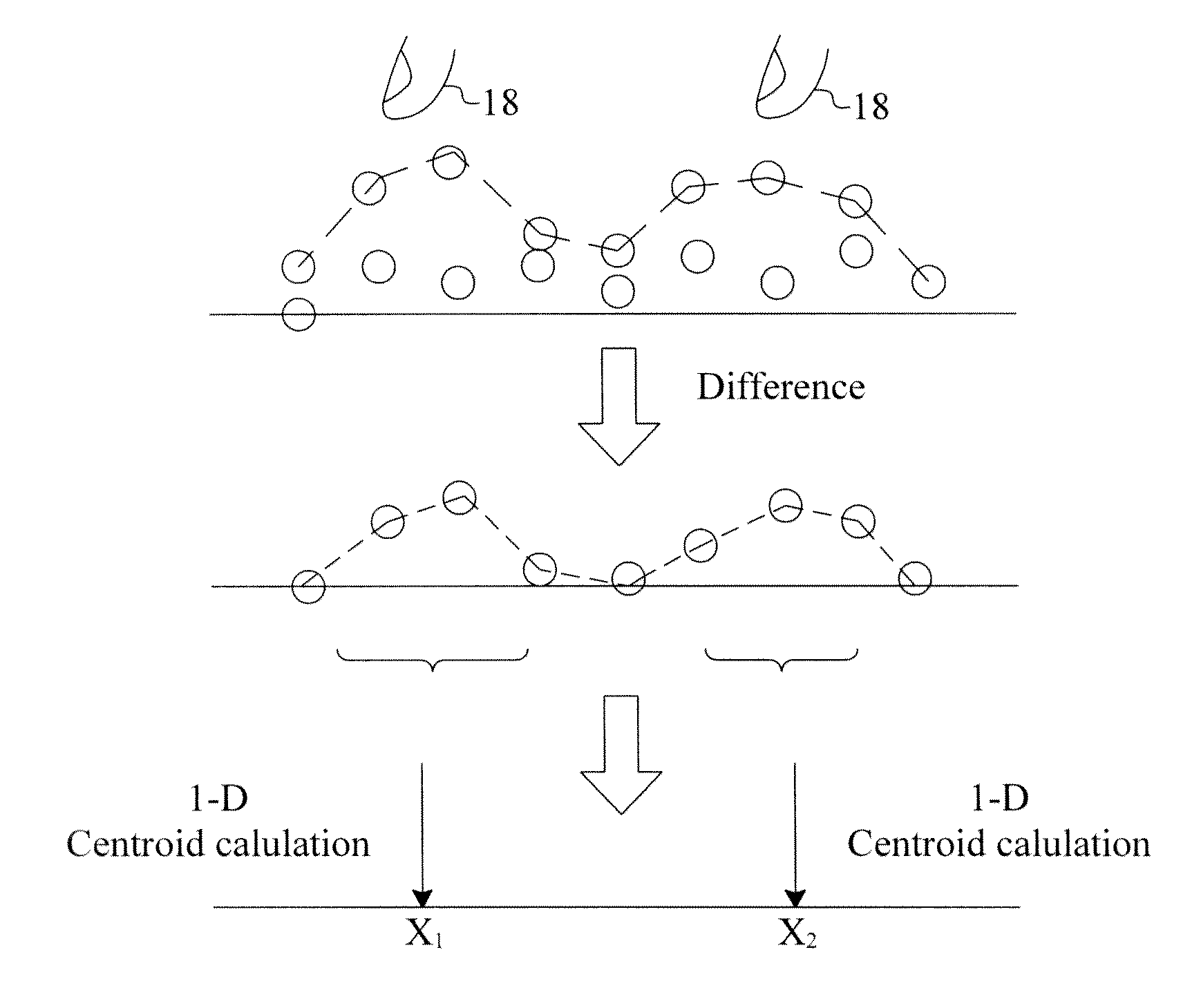
[0010]The present invention combines the advantages of both X-Y projected and all-point sensing to achieve higher frame rate

Problems solved by technology

Such a capacitive touch panel, though capable of yielding precise positional information of objects placed thereon, is disadvantaged by high costs and a huge amount of data calculation resulted from the large number of sensors and traces used.
For multi-finger applications, however, this positioning method may cause ghost point phenomenon.
Because of the ghost point phenomenon, the sensing circuit of an X-Y projected capacitive touch panel can

Method used


Image

  • Object positioning for an x-y projected capacitive touch panel
  • Object positioning for an x-y projected capacitive touch panel
  • Object positioning for an x-y projected capacitive touch panel

Examples


Example

[0033]FIG. 13 illustrates a first embodiment of hybrid sensing for an X-Y projected capacitive touch panel according to the present invention, in which blank blocks represent X-Y projected sensed frames and hatched blocks represent all-point sensed frames. In this periodic frame interleaving embodiment, each three times of X-Y projected sensing are followed by once of all-point sensing, so as not only to maintain a relatively small amount of calculation, but also to make timely correction when a ghost point is sensed, thereby accurately identifying the touch points. In other embodiments, the X-Y projected sensed frames and the all-point sensed frames may be mixed in different ways as needed.

Example

[0034]FIG. 14 is a flowchart of a second embodiment of hybrid sensing for an X-Y projected capacitive touch panel according to the present invention, in which after step 32 stars the process, step 34 carries out X-Y projected frame sensing, step 36 carries out finger number resolution, and step 38 identifies whether or not the finger number is greater than one. If not, the process returns to step 34 to generate a next X-Y projected sensed frame; if yes, the process goes to step 40 for all-point frame sensing to obtain the accurate finger positions, and step 42 carries out finger number resolution and step 44 identifies whether or not the finger number is greater than one. If yes, the process goes back to step 40 to generate a next all-point sensed frame; if not, the process returns to step 34 to generate a next X-Y projected sensed frame. This dynamic frame interleaving approach performs X-Y projected sensing and all-point sensing depending on the number of fingers.

Example

[0035]FIG. 15 illustrates a third embodiment of hybrid sensing for an X-Y projected capacitive touch panel according to the present invention, in which a capacitive touch panel 50 includes X-traces and Y-traces represented by dashed lines. Normally, the capacitive touch panel 50 performs the conventional X-Y projected sensing, but when ghost point phenomenon is present, as shown in FIG. 15 for example, the foregoing all-point sensing is applied to traces X5, X6, X13 and X14 and traces Y3, Y4, Y9 and Y10 where the ghost points may be, so as to distinguish the real points from the ghost points.

[0036]Readers may refer to U.S. Patent Application Publication No. 20100188364 for further details of the operation and principle of the aforesaid procedure of capacitance sensing under simultaneously charging two intersecting traces.

[0037]While the present invention has been described in conjunction with preferred embodiments thereof, it is evident that many alternatives, modifications and vari...


PUM


Abstract

Methods are proposed for object positioning for an X-Y projected capacitive touch panel. In an embodiment, capacitance sensing under inphase excitation of traces is applied to set a base value when the capacitive touch panel is not touched and to obtain capacitances at intersections when the capacitive touch panel is touched, and the base value is compared with the measured capacitances to identify touch points. In other embodiments, X-Y projected sensing and all-point sensing are combined to reduce the amount of calculation and achieve the same positioning effect as an all-point capacitive touch panel.

Description

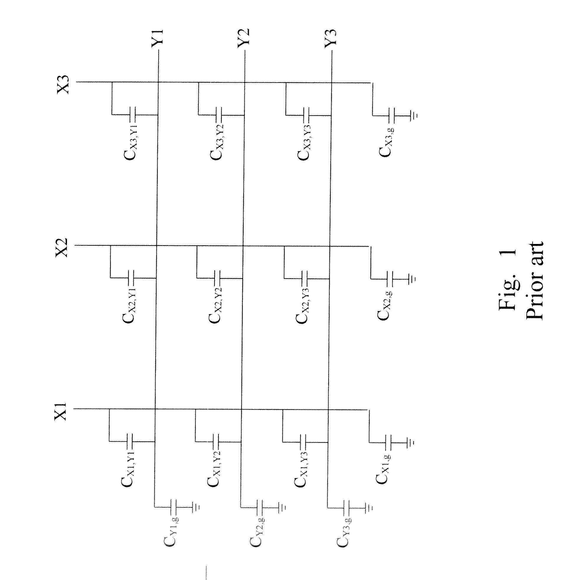
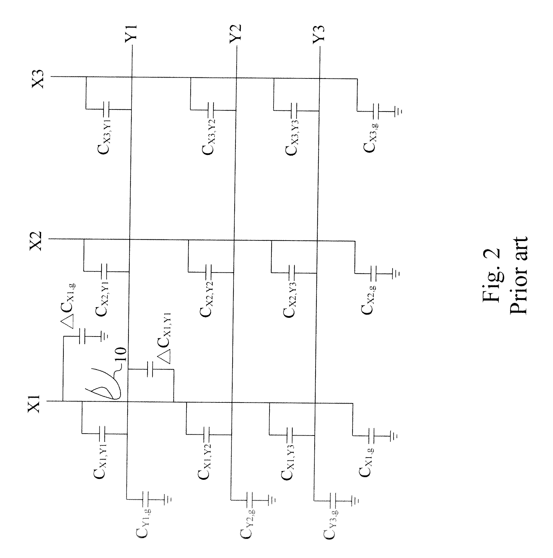
FIELD OF THE INVENTION[0001]The present invention is related generally to a capacitive touch panel and, more particularly, to positioning methods for a two-dimensional capacitive touch panel.BACKGROUND OF THE INVENTION[0002]Capacitive touch panels can be divided by their trace arrangements and positioning methods into the all-point type and the two-dimensional type. An all-point capacitive touch panel includes a plurality of discrete sensors arranged in a matrix and connected to a detector circuit via their respective independent traces. Such a capacitive touch panel, though capable of yielding precise positional information of objects placed thereon, is disadvantaged by high costs and a huge amount of data calculation resulted from the large number of sensors and traces used.[0003]On the other hand, a two-dimensional capacitive touch panel, also known as an X-Y projected capacitive touch panel, as shown in FIG. 1, includes sensors composed of intersecting X-traces and Y-traces, and...

Claims


Application Information

Patent Timeline
IPC IPC(8): G06F3/041
CPCG06F3/0416G06F2203/04104G06F3/044G06F3/04166G06F3/0446
Inventor LIN, CHIA-HSINGTAO, YI-HSINNIEN, HUNGSUNG, BRIANTSAI, HSIN-SHIEHTSENG, HSUAN-WEN
Owner ELAN MICROELECTRONICS CORPORATION
Why Eureka
Try Eureka