low impedance display

A display, low-impedance technology, used in static indicators, instruments, etc., to solve problems such as inability to charge pixels to the expected voltage potential

Active Publication Date: 2022-06-28
AU OPTRONICS CORP +1
View PDF12 Cites 0 Cited by
  • Summary
  • Abstract
  • Description
  • Claims
  • Application Information

AI Technical Summary

Problems solved by technology

However, the multiplexer itself has a high equivalent impedance
Therefore, when the conventional flat-panel display has high resolution or high frame rate (frame rate), so that each pixel is only allocated a short data writing time, the conventional flat-panel display will face the inability to charge the pixel to the expected voltage Potential problem

Method used


Image

  • low impedance display
  • low impedance display
  • low impedance display

Examples


Embodiment Construction

[0052] Below in conjunction with accompanying drawing, structure principle and working principle of the present invention are described in detail:

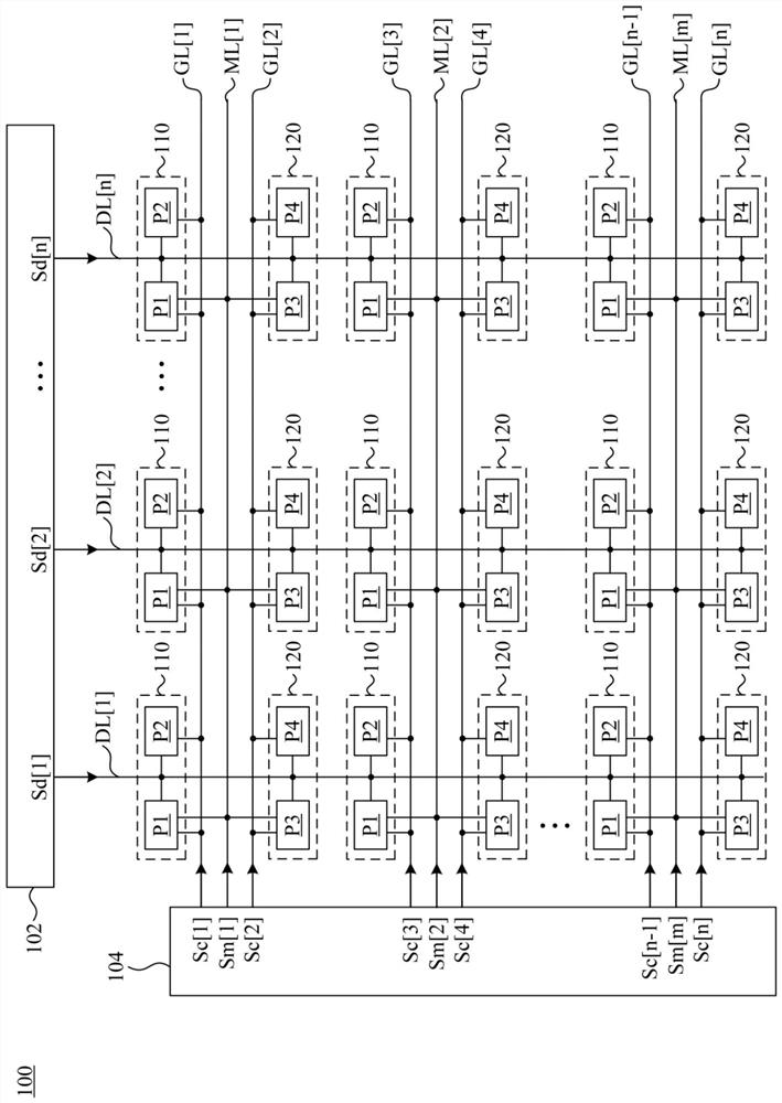
[0053] figure 1 It is a simplified functional block diagram of the low impedance display 100 according to an embodiment of the present invention. The low-impedance display 100 includes a source driver 102, a gate driver 104, a plurality of horizontal driving lines GL[1]-GL[n], a plurality of multiplexing driving lines ML[1]-ML[m], and a plurality of data lines DL[ 1 ]˜DL[n], a plurality of first pixel groups 110 and a plurality of second pixel groups 120 . The first pixel group 110 includes a first pixel P1 and a second pixel P2, and the second pixel group 120 includes a third pixel P3 and a fourth pixel P4. The horizontal driving lines GL[1]-GL[n] are used to receive control signals Sc[1]-Sc[n] from the gate driver 104, respectively. The multiplexing driving lines ML[1]-ML[m] are used for receiving the multiplexing signals Sm[...


PUM


Abstract

A low impedance display includes a first pixel group, a second pixel group and a first multiplexing driving line. The first pixel group includes first pixels and second pixels. The second pixel group includes third pixels and fourth pixels, wherein the first pixel group and the second pixel group receive data signals from the data lines. The first multiplexing driving line is coupled to the first pixel and the third pixel for receiving the first multiplexing signal. The first multiplexing driving line is also used to control the first pixel and the second pixel to receive the data signal sequentially, and control the third pixel and the fourth pixel to receive the data signal sequentially.

Description

technical field [0001] The present invention relates to a display, in particular to a display that does not need a multiplexer between a source driver and a data line. Background technique [0002] In order to save cost, a conventional flat panel display will set a multiplexer between the source driver and the data line, so that a larger number of data lines can be driven by the source driver with fewer output pins. However, the multiplexer itself has a high equivalent impedance. Therefore, when a conventional flat panel display has a high resolution or a high frame rate so that each pixel is only allocated a short data writing time, the conventional flat panel display will face the inability to charge the pixel to the desired voltage potential problem. [0003] In view of this, how to provide a flat panel display that can be applied to high resolution and high frame rate is a problem to be solved in the industry. SUMMARY OF THE INVENTION [0004] The present invention ...

Claims


Application Information

Patent Timeline
Patent Type & Authority Patents(China)
IPC IPC(8): G09G3/20
CPCG09G3/20
Inventor 林志隆陈福星陈力荣张瑞宏陈柏澍许志丞白承丘
Owner AU OPTRONICS CORP
Why Eureka
Try Eureka