Boundary resolution improvement for a capacitive touch panel

a capacitive touch panel and bound resolution technology, applied in the direction of instruments, pulse techniques, keyboard-like device coding, etc., can solve the problem of user touch operation being useless

Inactive Publication Date: 2011-03-03
ELAN MICROELECTRONICS CORPORATION
View PDF1 Cites 11 Cited by
  • Summary
  • Abstract
  • Description
  • Claims
  • Application Information

AI Technical Summary

Benefits of technology

[0004]According to the present invention, a virtual trace outward of the boundary trace of a capacitive touch panel is defined and assigned with a virtual coordinat...

Problems solved by technology

All capacitive touch panels have such non-addressable region...

Method used


Image

  • Boundary resolution improvement for a capacitive touch panel
  • Boundary resolution improvement for a capacitive touch panel
  • Boundary resolution improvement for a capacitive touch panel

Examples


Embodiment Construction

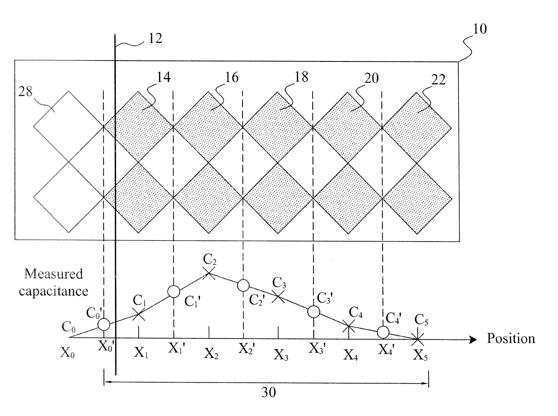
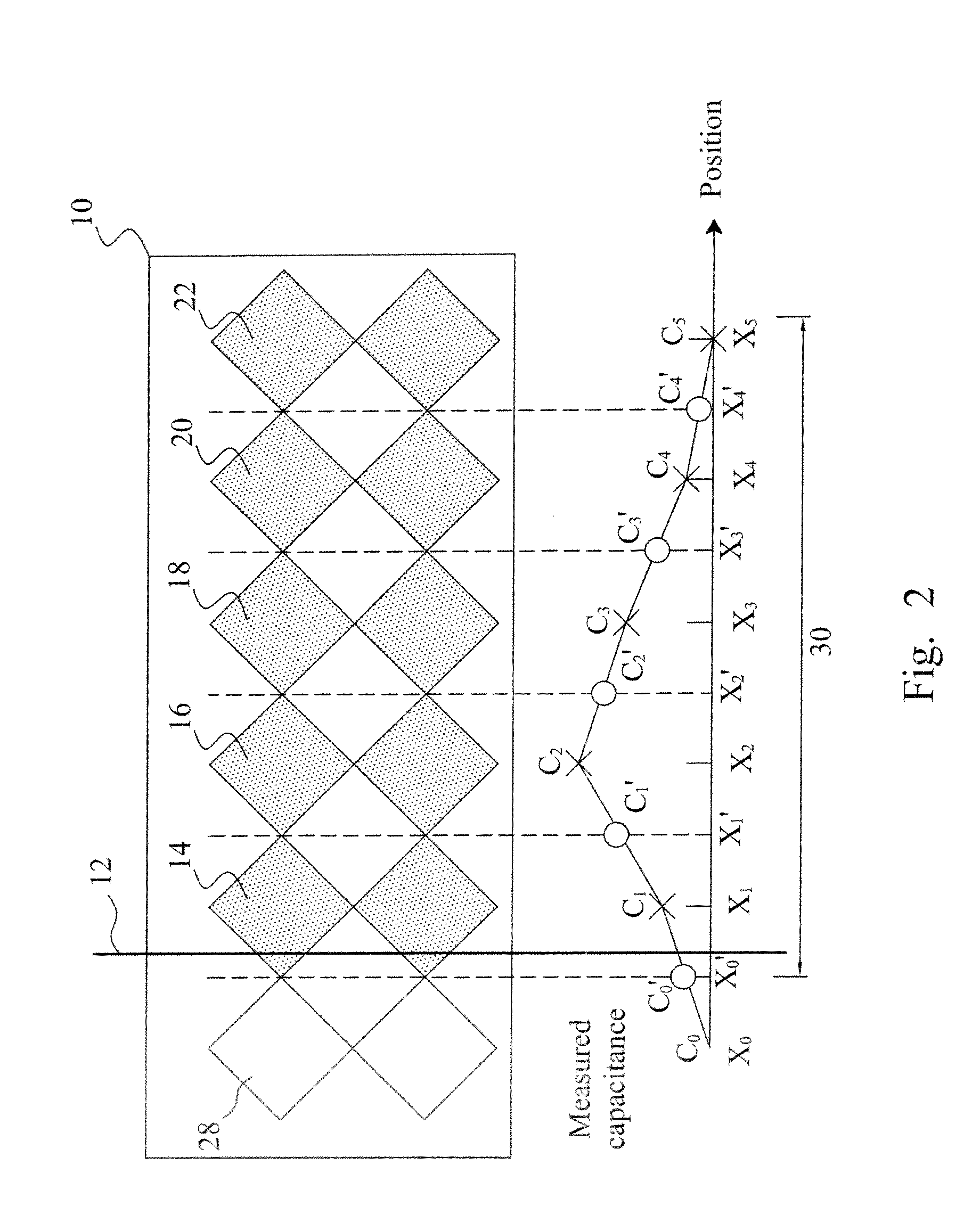
[0009]According to the present invention, as shown in FIG. 2, for a capacitive touch panel 10 having a plurality of traces 14, 16, 18, 20 and 22 in X-direction, a virtual trace 28 is defined outward of the boundary trace 14 and assigned with a virtual coordinate X0 in the X-direction. The term “virtual” indicates the trace 28 not physical or hardware as are the traces 14, 16, 18, 20 and 22. When the capacitive touch panel 10 is touched, the capacitances of the touched physical traces are changed, and the measured capacitances Cm from the physical traces 14, 16, 18, 20 and 22 are converted by an analog-to-digital converter (not shown in FIG. 2) into digital values. For interpolation to calculate the coordinate X of the touch point, a virtual measured capacitance C0 is assigned to the virtual trace 28. For example, in this embodiment, the virtual measured capacitance C0 is preset at zero. In order to determine the coordinate X of the touch point, the mean coordinates of each two adjac...


PUM


Abstract

A capacitive touch panel has a plurality of traces including a boundary trace, and a virtual trace is defined outward of the boundary trace and assigned with a virtual coordinate and a virtual capacitance for interpolation to position a touch point around the boundary of the capacitive touch panel, thereby eliminating the non-addressable region of the capacitive touch panel.

Description

FIELD OF THE INVENTION[0001]The present invention is related generally to a capacitive touch panel and, more particularly, to a positioning method for a capacitive touch panel.BACKGROUND OF THE INVENTION[0002]As shown in FIG. 1, a capacitive touch panel 10 has a plurality of traces 14, 16, 18, 20 and 22 in X-direction, which are assigned with the coordinates X1, X2, X3, X4 and X5 respectively, from the boundary 12 to the right. Each coordinate Xm represents where the center of the corresponding trace is in the X-direction, and the coordinate Xm may be a relative coordinate or an absolute coordinate in the X-direction. When the capacitive touch panel 10 is touched, the capacitances of the touched traces are changed. By sensing the traces 14, 16, 18, 20 and 22 for the capacitances thereon, the measured capacitances Cm, typically converted by an analog-to-digital converter (not shown in FIG. 1) into digital values, are used together with the coordinate Xm for interpolation to position ...

Claims


Application Information

Patent Timeline
IPC IPC(8): G06F3/045H03K17/94
CPCG06F3/044
Inventor NIEN, HUNGTAO, YI-HSINTENG, CHIH-HSIENTSAI, HSIN-SHIEHHUANG, CHUN-CHUNGLIN, CHIA-HSING
Owner ELAN MICROELECTRONICS CORPORATION
Why Eureka
Try Eureka