Switching hub and ring network

a hub and ring network technology, applied in data switching networks, frequency-division multiplexes, instruments, etc., can solve the problems of overflow of fdb entries with increasing number of terminals to connect, increased cpu load to manage them, unnecessary flood relays, etc., to reduce the amount of learning, reduce the size of the table, and reduce the effect of cos

Inactive Publication Date: 2011-03-03
APRESIA SYST LTD
View PDF6 Cites 4 Cited by
  • Summary
  • Abstract
  • Description
  • Claims
  • Application Information

AI Technical Summary

Benefits of technology

[0039]According to the embodiments of the invention, when one of the two ring ports receives the frame and when a VLAN in which the received frame belongs is a VLAN only through both the ring ports, the forwarding processing mechanism forwards the frame to the other ring port without performing FDB learning on the frame. The switching hub can therefore reduce amounts to be learned by its FDB. This can reduce the size of the table of the FDB, and therefore contribute to cost reduction, while making it possible to inhibit the overflow of entries in the FDB, and therefore reduce unnecessary flood relays. Also, it is possible to reduce CPU load for the administration of the FDB, such as PDB erase for switching in case of failure.

Problems solved by technology

Because the conventional switching hub performs the FDB learning of receiving ports, source MAC addresses, and VLAN-IDs for all of received frames, the conventional switching hub is, however, likely to cause the overflow of entries in the FDB with increasing number of terminals to connect.
There therefore arises the problem that unnecessary flood relays are performed, to waste transmission line bands.
There also arises the problem that, with further increasing number of entries in the FDB, the CPU load to manage them is increased.
In this case, there is also the problem that the erasure of the FDB is time consuming when the FDB contains large numbers of entries.

Method used


Image

  • Switching hub and ring network
  • Switching hub and ring network
  • Switching hub and ring network

Examples


first embodiment

[0048]Below is described a preferred embodiment according to the invention, referring to FIGS. 1, 2, and 3.

[0049]Ring Network 10 Configuration

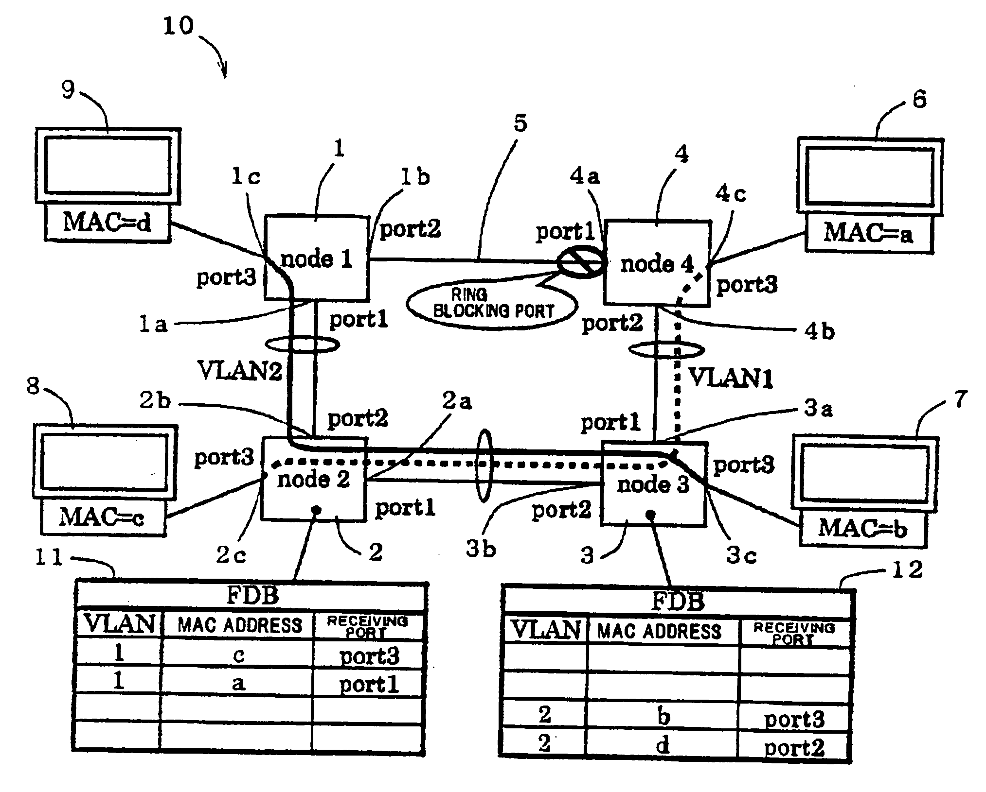
[0050]FIG. 1 is a diagram showing a ring network in this embodiment.

[0051]As shown in FIG. 1, a ring network 10 is configured to connect first, second, third, and fourth switching hubs 1, 2, 3, and 4 (in the figure, also referred to as node 1, node 2, node 3, and node 4, respectively) in a ring shape.

[0052]The first switching hub 1 has first, second, and third ports 1a, 1b, and 1c (in the figure, also referred to as port 1, port 2, and port 3, respectively). Likewise, the second switching hub 2 has first, second, and third ports 2a, 2b, and 2c, the third switching hub 3 has first, second, and third ports 3a, 3b, and 3c, and the fourth switching hub 4 has first, second, and third ports 4a, 4b, and 4c.

[0053]The respective first ports 1a to 4a and second ports 1b to 4b of the first to fourth switching hubs 1 to 4 are the ring ports to be connect...

second embodiment

[0087]FIG. 4 shows a switching hub 40 in another embodiment according to the invention.

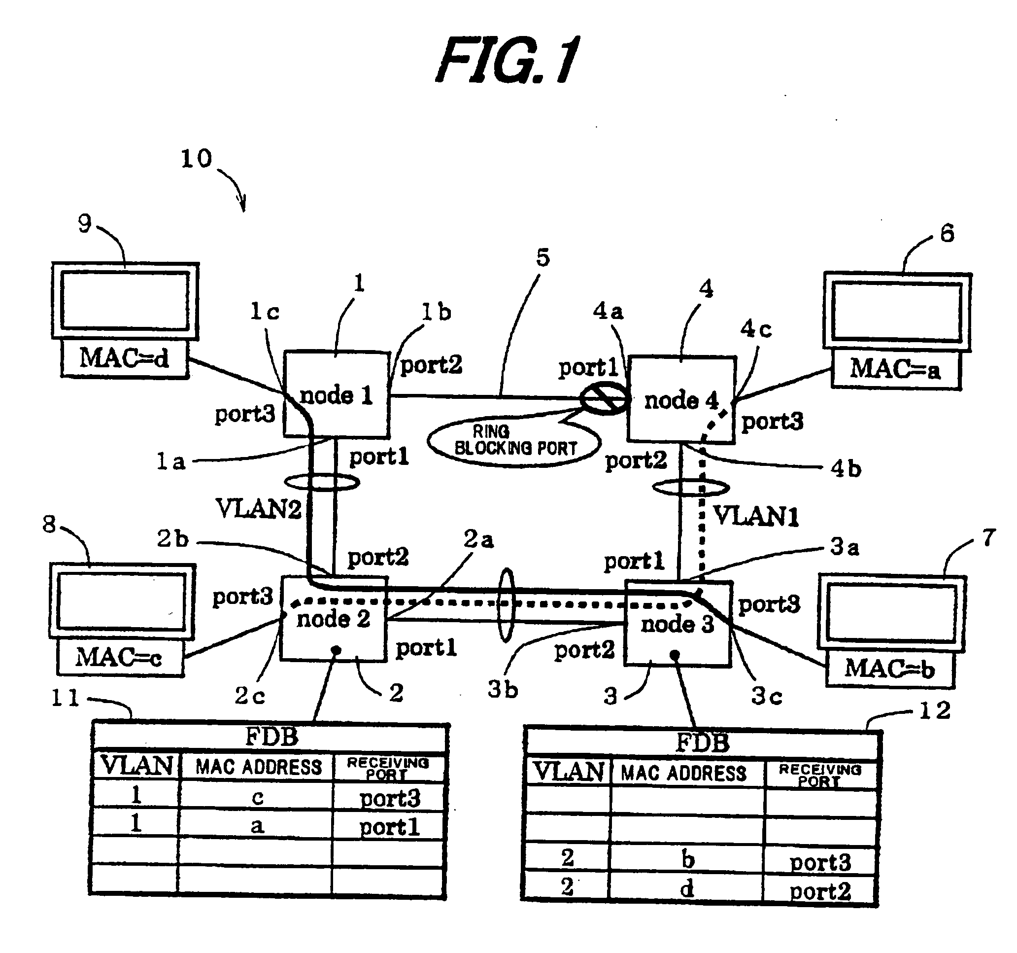
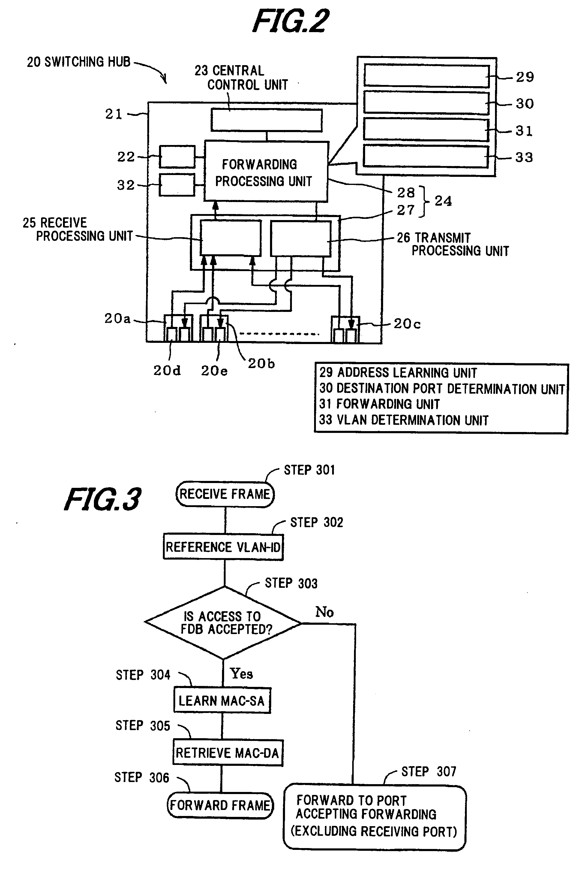
[0088]Although in the embodiment of FIG. 2, the acceptance / rejection of access to the FDB 22 for each VLAN, and the acceptance / rejection of forwarding to each port for each VLAN have been set in the VLAN setting table 32, only the acceptance / rejection of access to the FDB 22 for each VLAN may be set in the VLAN setting table 32, and a separate VLAN filtering table 41 may, as shown in FIG. 4, be provided to set the acceptance / rejection of forwarding to each port for each VLAN in the VLAN filtering table 41. In this case, a setting example of the VLAN setting table 32 and the VLAN filtering table 41 of the second switching hub 2 is shown in Table 3, and a setting example of the VLAN setting table 32 and the VLAN filtering table 41 of the third switching hub 3 is shown in Table 4.

TABLE 3VLAN setting tableVLAN filtering tableVLANAccess to FDBVLANport 1port 2port 31Accepted1AcceptedRejectedAccepted2Rej...


PUM


Abstract

A switching hub for processing a VLAN frame transmitted through a transmission line of a ring network includes two ring ports connected to the transmission line of the ring network, and a forwarding processing mechanism for, when one of the two ring ports receives the frame and when a VLAN in which the received frame belongs is a VLAN only through both the ring ports, forwarding the frame to the other ring port without performing FDB learning on the frame.

Description

[0001]The present application is based on Japanese patent application No. 2009-203762 filed on Sep. 3, 2009, the entire contents of which are incorporated herein by reference.BACKGROUND OF THE INVENTION[0002]1. Field of the Invention[0003]The present invention relates to a switching hub connected in a ring shape to constitute a ring network, and a ring network.[0004]2. Description of the Related Art[0005]In conventional LAN (local area network) architecture, a technology is widely used that configures the network to physically include a loop, but to logically disconnect one portion of the loop, and thereby realize redundancy in case of network failure. As one example, a redundancy technology with a ring network 100 as shown in FIG. 6 has been proposed.[0006]The ring network 100 is configured to connect first, second, third, and fourth switching hubs 101, 102, 103, and 104 (in the figure, also referred to as node 1, node 2, node 3, and node 4, respectively) in a ring shape. The first...

Claims


Application Information

Patent Timeline
Patent Type & Authority Applications(United States)
IPC IPC(8): H04L12/28
CPCH04L12/4641H04L12/433
Inventor SETO, KOICHIROAOSHIMA, KENJI
Owner APRESIA SYST LTD
Why Eureka
Try Eureka