Ceramic turbine shroud support

a ceramic turbine and shroud support technology, applied in the direction of machines/engines, stators, liquid fuel engines, etc., can solve the problems of low thermal expansion of ceramics that make up the blades and ibrs, exacerbate the issue further, and reduce the performance of engines, reducing the effect of useful energy not being harnessed

Active Publication Date: 2011-03-03
RTX CORP
View PDF52 Cites 39 Cited by
  • Summary
  • Abstract
  • Description
  • Claims
  • Application Information

AI Technical Summary

Problems solved by technology

In both cases, particularly that of a ceramic IBR, a large gap between rotor blade tip and metal shrouds commonly results from the low thermal expansion of ceramics that make up the blades and the IBRs.
The low density and high stiffness of ceramics reduce the radial displacement of the blade tip and therefore exacerbates the issue further.
The large gap or clearance at the blade tip results in a high percentage of hot working medium gas flow leaking through the tip-shroud gap that reduces the transfer of energy from the gas flow to turbine blades, which in turn causes an engine performance penalty as useful energy is not harnessed.
The performance penalty is more severe for small gas turbine engines because the engine size makes a small tip clearance large relative to the gas flow path.
The main difficulty in ceramic shroud design is the attachment to the metallic engine structure because of low ductility and low thermal expansion of ceramics relative to metals.
Elastic springs have been used to support ceramic shrouds, but their performance at elevated temperatures over long durations is questionable due to metal creep.
However, in practice, due to manufacturing tolerance control, uneven thermal fields, and thermal deformation of the shroud and the casing, thermal stress at the tabs may be sufficiently high to cause local damage.
However, it is difficult to control the clamp load from the shrink-fit metallic support on the shroud over a wide range of thermal transient conditions.

Method used


Image

  • Ceramic turbine shroud support
  • Ceramic turbine shroud support
  • Ceramic turbine shroud support

Examples


Embodiment Construction

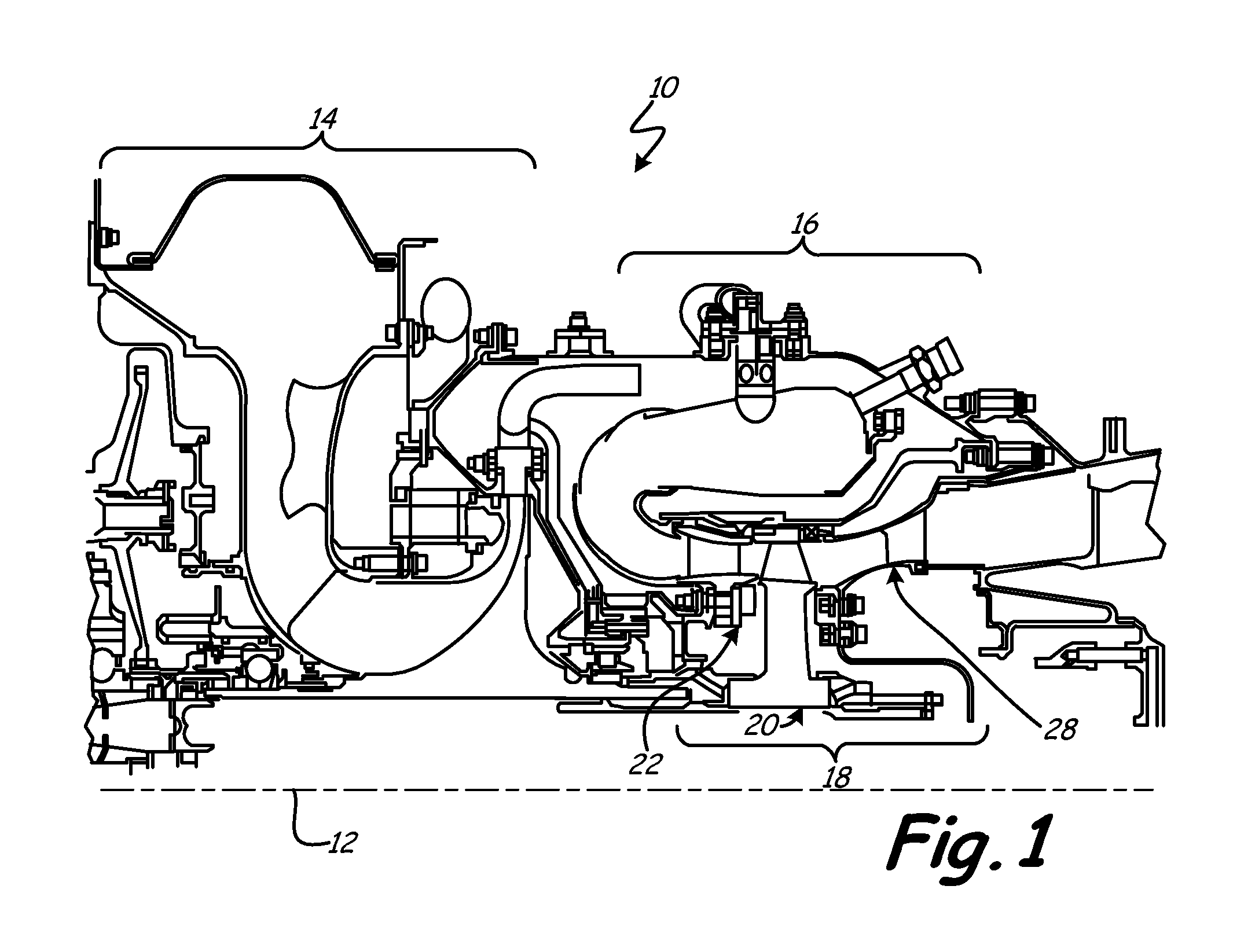
FIG. 1 is an axial cross-section of gas turbine engine 10 including engine axis 12, compressor 14, combustor 16, and turbine 18. A working medium fluid, such as air, is pulled into the front of engine 10 by, for example, a fan (not shown) and directed into compressor 14. The air stream is successively compressed through stages of compressor 14 and directed into combustor 16. In combustor 16, the air stream is mixed with fuel and ignited. The air and fuel mixture ignited in combustor section 16 is directed into turbine 18 in which the mixture is successively expanded through alternating stages of turbine rotors, such as rotor 20 and stators, such as stator 22. A portion of the gas and fuel mixture leaving combustor 16 acts to rotate turbine 18, which powers compressor 14. The remaining portion of the gas and fuel mixture passing through turbine 18 exits the back of engine 10 to provide thrust for engine 10.

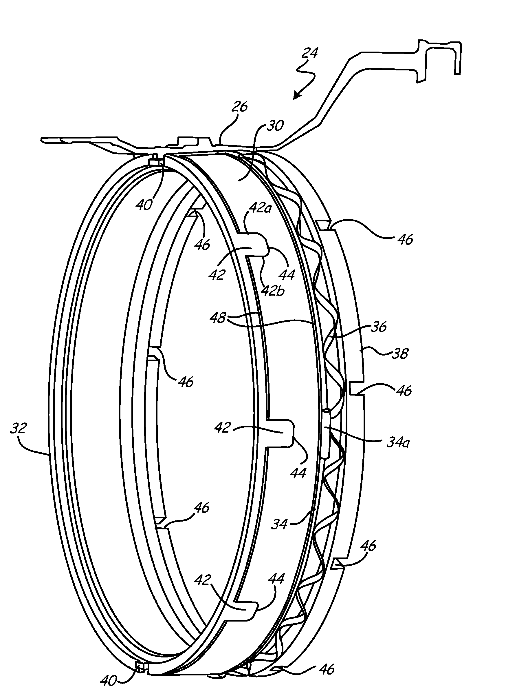
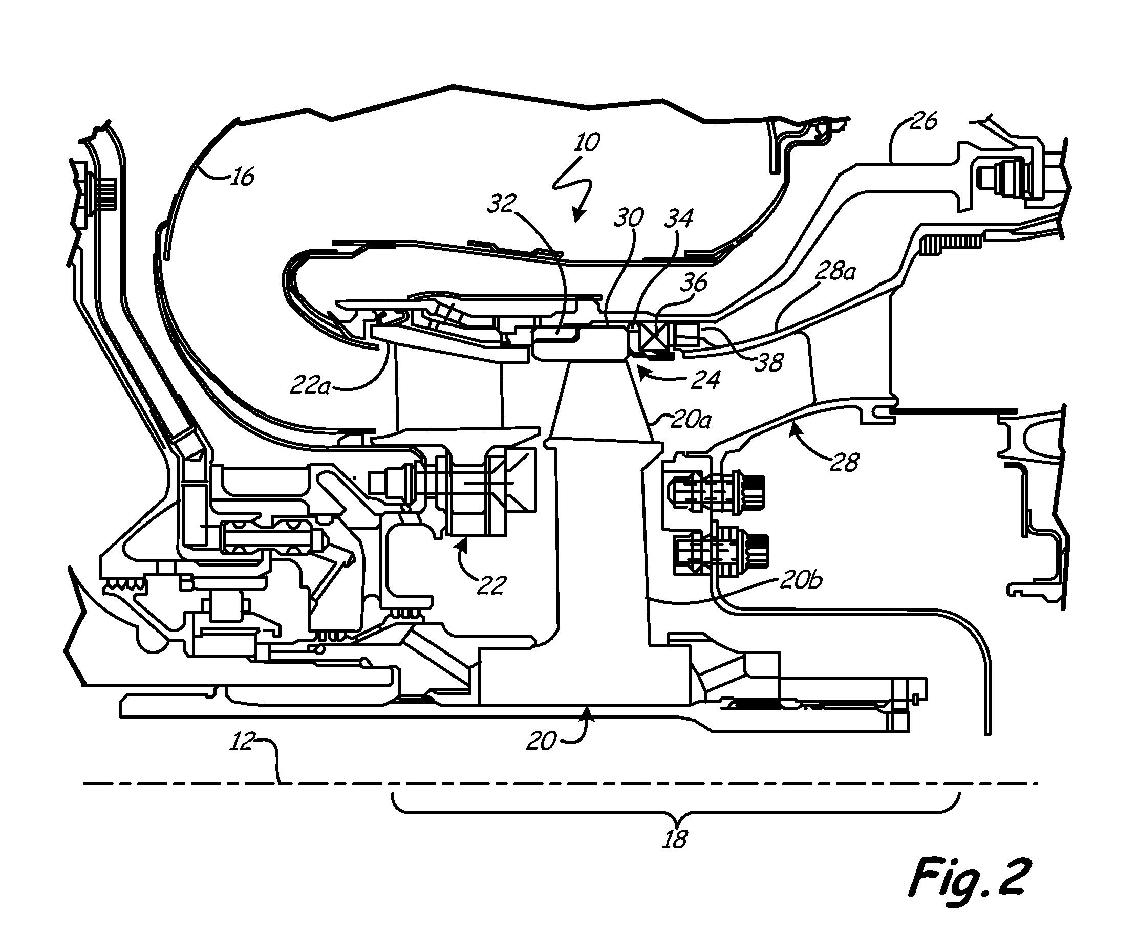
FIG. 2 is a detail section view of gas turbine engine 10 including rotor 20, s...


PUM

PropertyMeasurementUnit
resilientaaaaaaaaaa
softaaaaaaaaaa
thrustaaaaaaaaaa

Abstract

A turbine shroud includes a ceramic shroud ring configured to surround a plurality of turbine rotor blades, a plurality of slots circumferentially distributed around the ceramic shroud ring, a forward metallic support ring, a plurality of tabs attached to a forward edge of the forward metallic support ring configured to engage a turbine support case, and a plurality of tabs attached to an aft edge of the forward metallic support ring received by the slots of the ceramic shroud ring. Only two axially extending radial surfaces of each of the tabs attached to the aft edge of the forward metallic support ring are configured to contact the slots of the ceramic shroud ring.

Description

BACKGROUNDThe present invention relates to turbine engines. In particular, the present invention relates to devices for attaching ceramic turbine shrouds to surrounding metallic turbine components.A gas turbine engine commonly includes a fan, a compressor, a combustor, a turbine, and an exhaust nozzle. During engine operation, working medium gases, for example air, are drawn into and compressed in the compressor. The compressed air is channeled to the combustor where fuel is added to the air and the air / fuel mixture is ignited. The products of combustion are discharged to the turbine section, which extracts work from these products to produce useful thrust to power, for example, an aircraft in flight. A portion of the work extracted from the products of combustion by the turbine is used to power the compressor.The compressor and turbine commonly include alternating stages of rotor blades and stator vanes. Compressor and turbine rotors include stationary annular fluid seals surroundi...

Claims


Application Information

Patent Timeline
Patent Type & Authority Applications(United States)
IPC IPC(8): F01D9/04
CPCF01D9/04F01D11/08F01D25/246F05D2300/21F05D2230/642Y02T50/67Y02T50/60
Inventor SHI, JUNGREEN, KEVIN E.REINHARDT, GREGORY E.
Owner RTX CORP
Why Eureka
Try Eureka