Fuel cell stack

a technology of fuel cell stack and stacking, which is applied in the direction of fuel cells, cell components, fuel cell grouping, etc., can solve the problems of difficult to allocate the same flow rate of coolant to the pair of left and right holes, the pressure loss in the manifold is reduced, and the cooling effect is simple and uniform

Active Publication Date: 2011-03-03
HONDA MOTOR CO LTD
View PDF5 Cites 10 Cited by
  • Summary
  • Abstract
  • Description
  • Claims
  • Application Information

AI Technical Summary

Benefits of technology

[0012]The present invention has been made to solve the problems of this type, and an object of the present invention is to provide a fuel cell stack having simple structure which makes it possible to suitably reduce the pressure loss in a manifold, and smoothly and uniformly supply a coolant to fuel cells.

Problems solved by technology

As a consequence, the coolant cannot be supplied suitably to the pair of holes 5a.
The same problem may occur also in the discharge manifold.
However, in the structure, it is difficult to allocate the same flow rate of coolant to the pair of left and right holes 5a.
Therefore, the temperature distribution in the surfaces of the fuel cell become non-uniform, and the power generation performance of the fuel cell is low.

Method used


Image

  • Fuel cell stack
  • Fuel cell stack
  • Fuel cell stack

Examples


first embodiment

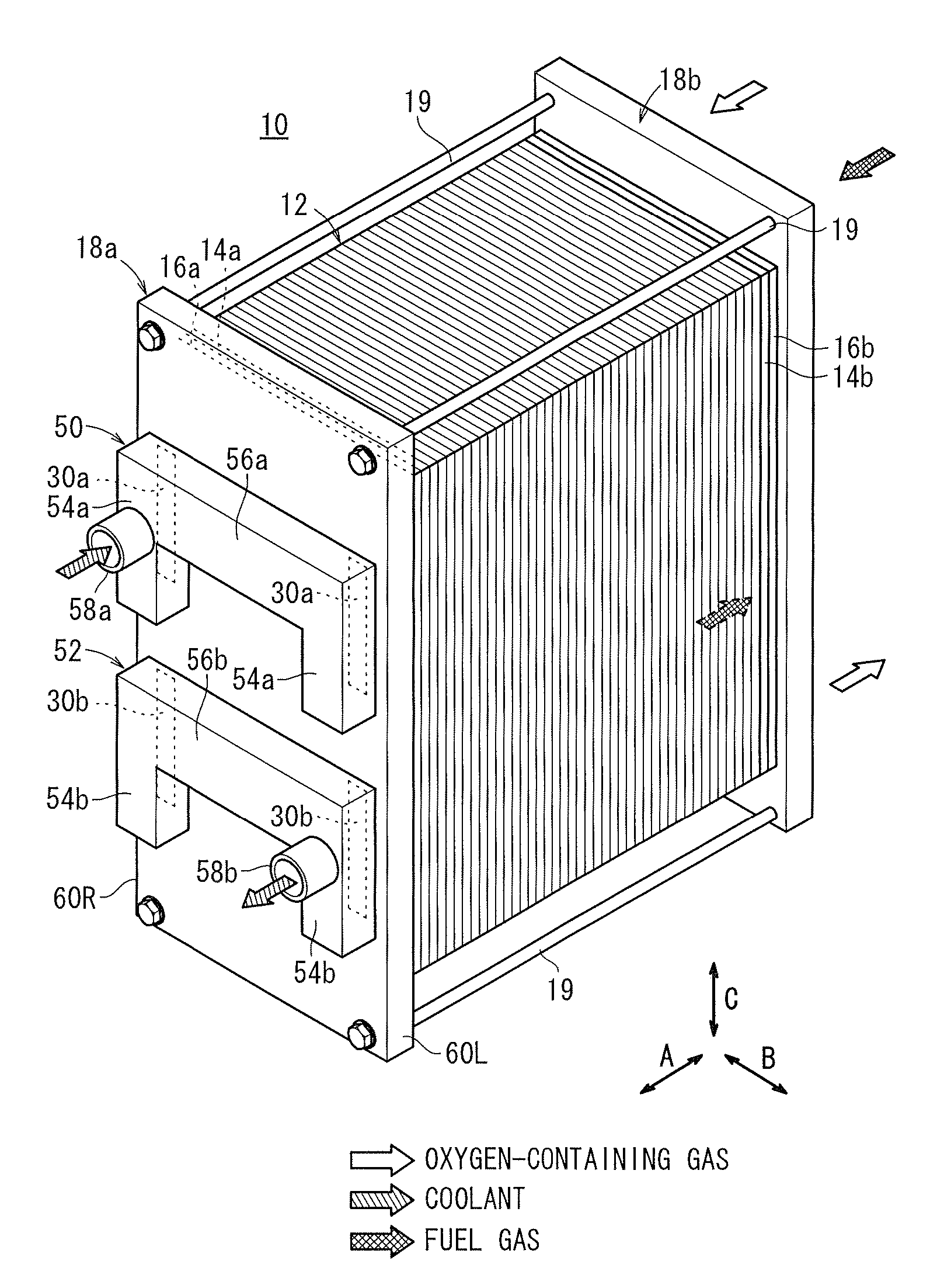
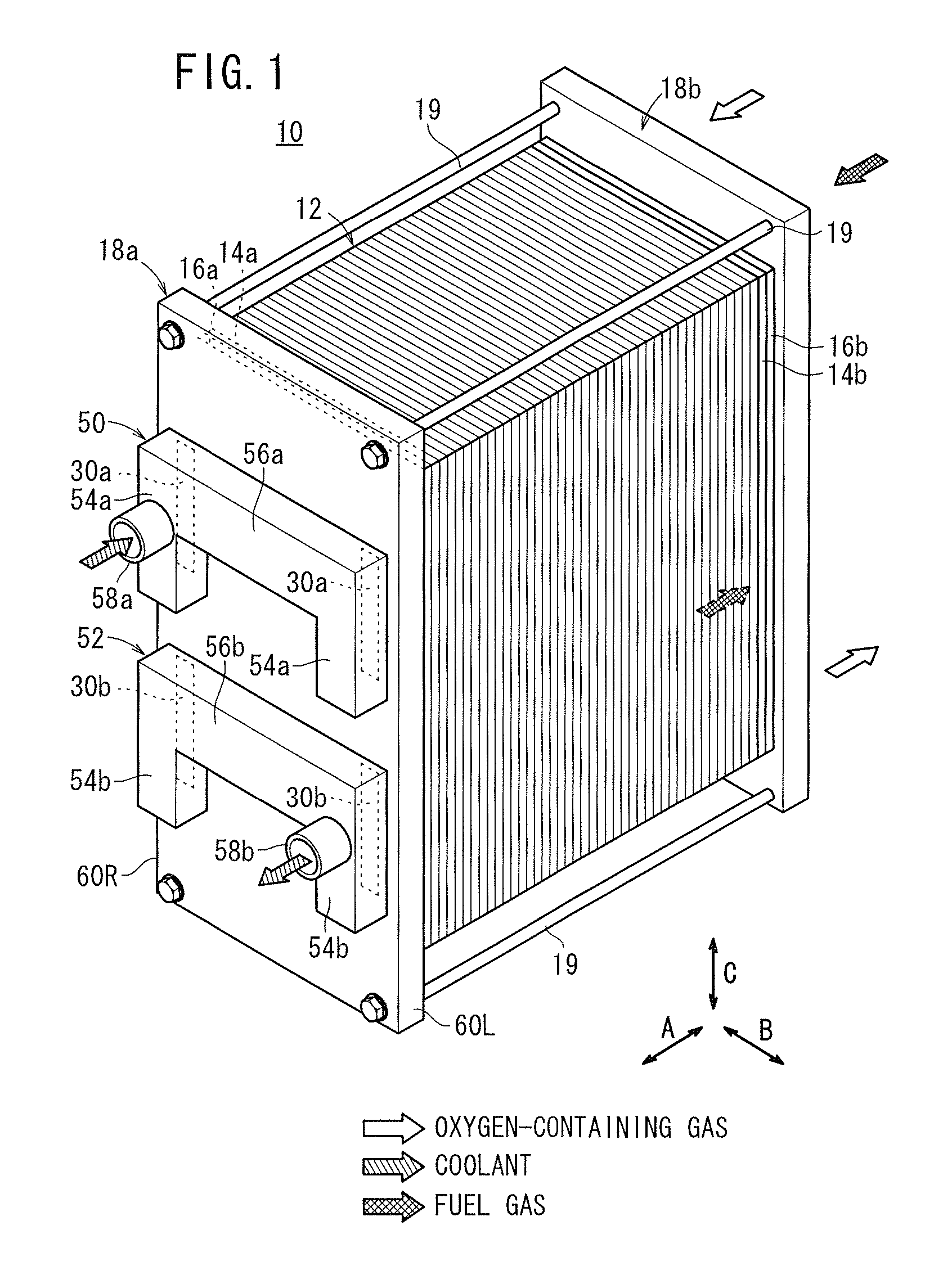
[0034]As shown in FIG. 1, a fuel cell stack 10 according to the present invention is formed by stacking fuel cells 12 in a horizontal direction indicated by an arrow A or in a vertical direction indicated by an arrow C.

[0035]A first terminal plate 14a, a first insulating plate 16a, and a first end plate 18a are stacked on one end of the fuel cells 12 in the stacking direction. Further, a second terminal plate 14b, a second insulating plate 16b, and a second end plate 18b are stacked on the other end of the fuel cells 12 in the stacking direction.

[0036]Components between the first end plate 18a and the second end plate 18b each having a rectangular shape are tightened together by a plurality of tie-rods 19 extending in the direction indicated by the arrow A. Alternatively, components of the fuel cell stack 10 are held together by a box-shaped casing (not shown) including the first end plate 18a and the second end plate 18b.

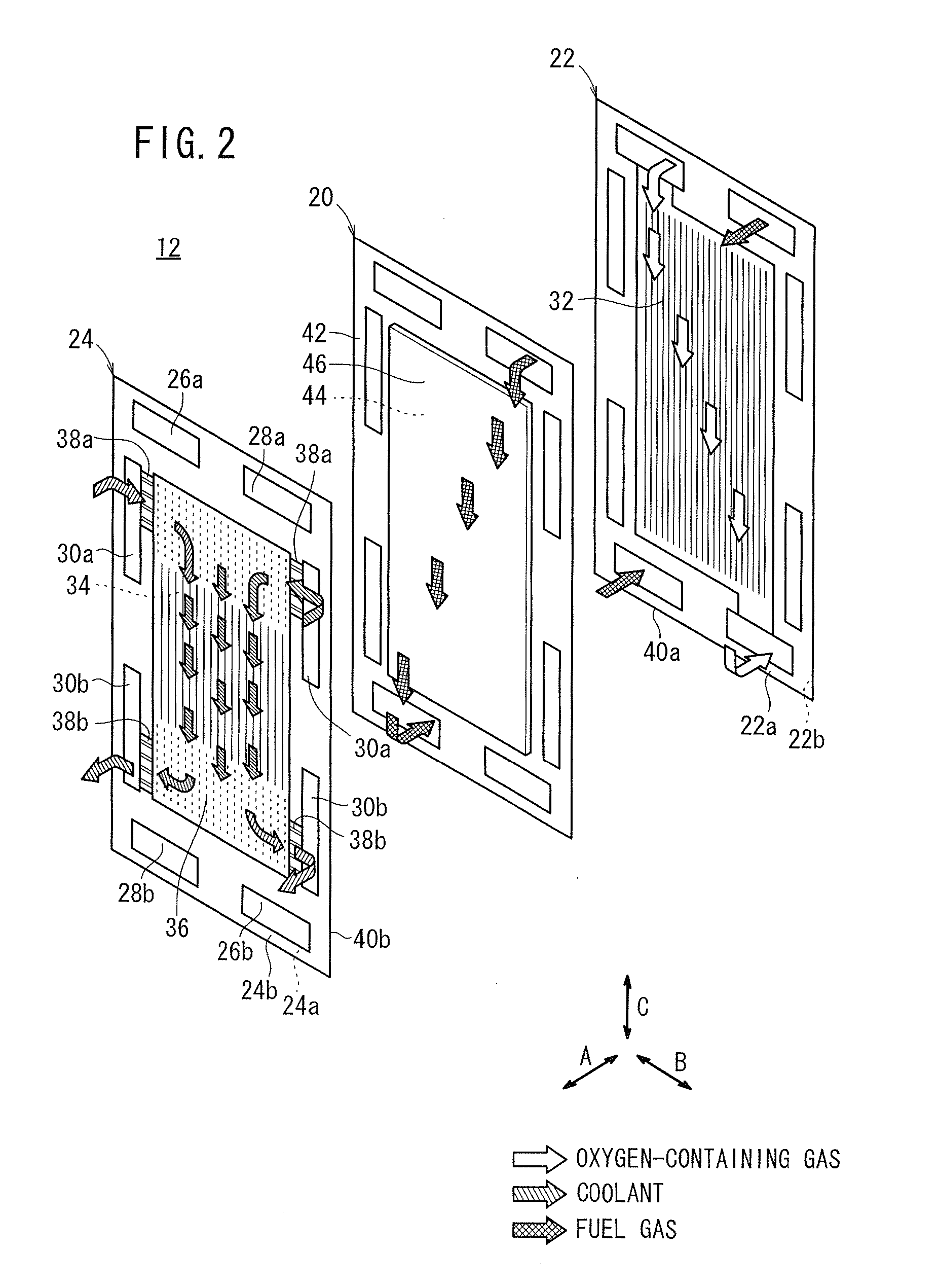
[0037]As shown in FIG. 2, the fuel cell 12 is formed by stac...

second embodiment

[0074]FIG. 8 is a perspective view with partial omission of a fuel cell stack 70 according to the present invention.

[0075]The constituent elements that are identical to those of the fuel cell stack 10 according to the first embodiment are labeled with the same reference numerals, and detailed descriptions thereof will be omitted. Also, in third or further embodiments described later, the constituent elements that are identical to those of the fuel cell stack 10 according to the first embodiment are labeled with the same reference numerals, and detailed descriptions thereof will be omitted.

[0076]The fuel cell stack 70 includes a coolant supply manifold 72 and a coolant discharge manifold 74 provided on the outer surface of the first end plate 18a. Each of the coolant supply manifold 72 and the coolant discharge manifold 74 has substantially an H-shape.

[0077]The coolant supply manifold 72 includes a pair of longitudinally elongated supply manifold sections 76a and a supply coupling se...

third embodiment

[0081]FIG. 9 is a perspective view with partial omission of a fuel cell stack 90 according to the present invention.

[0082]The fuel cell stack 90 includes a coolant supply manifold 92 and a coolant discharge manifold 94 provided on the other surface of the first end plate 18a. Each of the coolant supply manifold 92 and the coolant discharge manifold 94 has a substantially U-shape which is opened upward.

[0083]The coolant supply manifold 92 includes a pair of longitudinally elongated supply manifold sections 96a and a supply coupling section 98a coupling lower portions of the pair of supply manifold sections 96a together. The pair of supply manifold sections 96a are connected to the pair of coolant supply passages 30a. The width of the supply coupling section 98a (along the long sides in the longitudinal direction indicated by the arrow C) is smaller than the width of the pair of supply manifold sections 96a (along the long sides in the longitudinal direction indicated by the arrow C)....


PUM

PropertyMeasurementUnit
widthaaaaaaaaaa
areaaaaaaaaaaa
internal volumeaaaaaaaaaa

Abstract

A coolant supply manifold and a coolant discharge manifold are provided on a first end plate of a fuel cell stack. The coolant supply manifold includes a pair of supply manifold sections and a supply coupling section coupling upper portions of the pair of supply manifold sections together. The supply manifold sections are connected to a pair of coolant supply passages of a first end plate. The width of the coupling section is smaller than the width of the pair of supply manifold sections in a longitudinal direction along the long sides of the first end plate. A supply pipe extending to the outside of the first end plate is formed integrally with one of the supply manifold sections.

Description

CROSS-REFERENCE TO RELATED APPLICATION[0001]This application is based upon and claims the benefit of priority from Patent Applications No. 2009-202470 filed on Sep. 2, 2009, and No. 2009-205929 filed on Sep. 7, 2009, in the Japan Patent Office, of which the contents are incorporated herein by reference.BACKGROUND OF THE INVENTION[0002]1. Field of the Invention[0003]The present invention relates to a fuel cell stack formed by stacking an electrolyte electrode assembly and a pair of separators in a stacking direction, the electrolyte electrode assembly being interposed between the pair of separators. The electrolyte electrode assembly includes a pair of electrodes and an electrolyte interposed between the electrodes. Rectangular end plates are provided at both ends of the fuel cell stack in the stacking direction.[0004]2. Description of the Related Art[0005]For example, a solid polymer electrolyte fuel cell employs a membrane electrode assembly (MEA) which includes an anode, a cathode...

Claims


Application Information

Patent Timeline
Patent Type & Authority Applications(United States)
IPC IPC(8): H01M8/24H01M8/04
CPCH01M8/04029Y02E60/50H01M8/2485H01M8/241H01M8/0258H01M8/0267H01M8/2483H01M8/242
Inventor KOBAYASHI, NORIHISASUZUKI, MASAHARU
Owner HONDA MOTOR CO LTD
Why Eureka
Try Eureka