
Retaining device for cable lugs

a technology of retaining device and cable lug, which is applied in the direction of multiple conductor connector, line/current collector details, electrical apparatus, etc., can solve the problems of reducing the production efficiency of holding arrangement, and reducing the production efficiency of such a holding arrangemen

Active Publication Date: 2011-03-03
NEWFREY +1
View PDF9 Cites 22 Cited by
  • Summary
  • Abstract
  • Description
  • Claims
  • Application Information

AI Technical Summary

Benefits of technology

[0015]The holding arrangement according to the invention has the advantage that the connection sections, which are held in the holding device in such a way that they cannot become detached, of the connection elements are centered by centering means, which act on the outer circumference of the connection sections. Centering via a disposable part is therefore not required. Instead it is possible for the holding device to remain on the ground contact once the ground contact has been installed. This means that no waste products are produced in the fitting process.
[0060]In addition, the cable lugs are centered in the holding arrangement for the purpose of simple final assembly.

Problems solved by technology

The fitting complexity involved here is relatively great.
In addition, there is the risk of a cable lug of a cable harness, which is supplied by a cable harness manufacturer, being forgotten during the final fitting on the ground bolt.
The production of such a holding arrangement is comparatively complex, however.

Method used


Image

  • Retaining device for cable lugs
  • Retaining device for cable lugs
  • Retaining device for cable lugs

Examples


Embodiment Construction

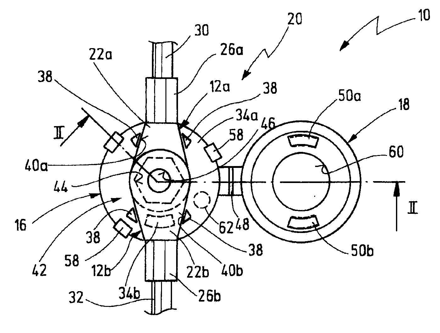
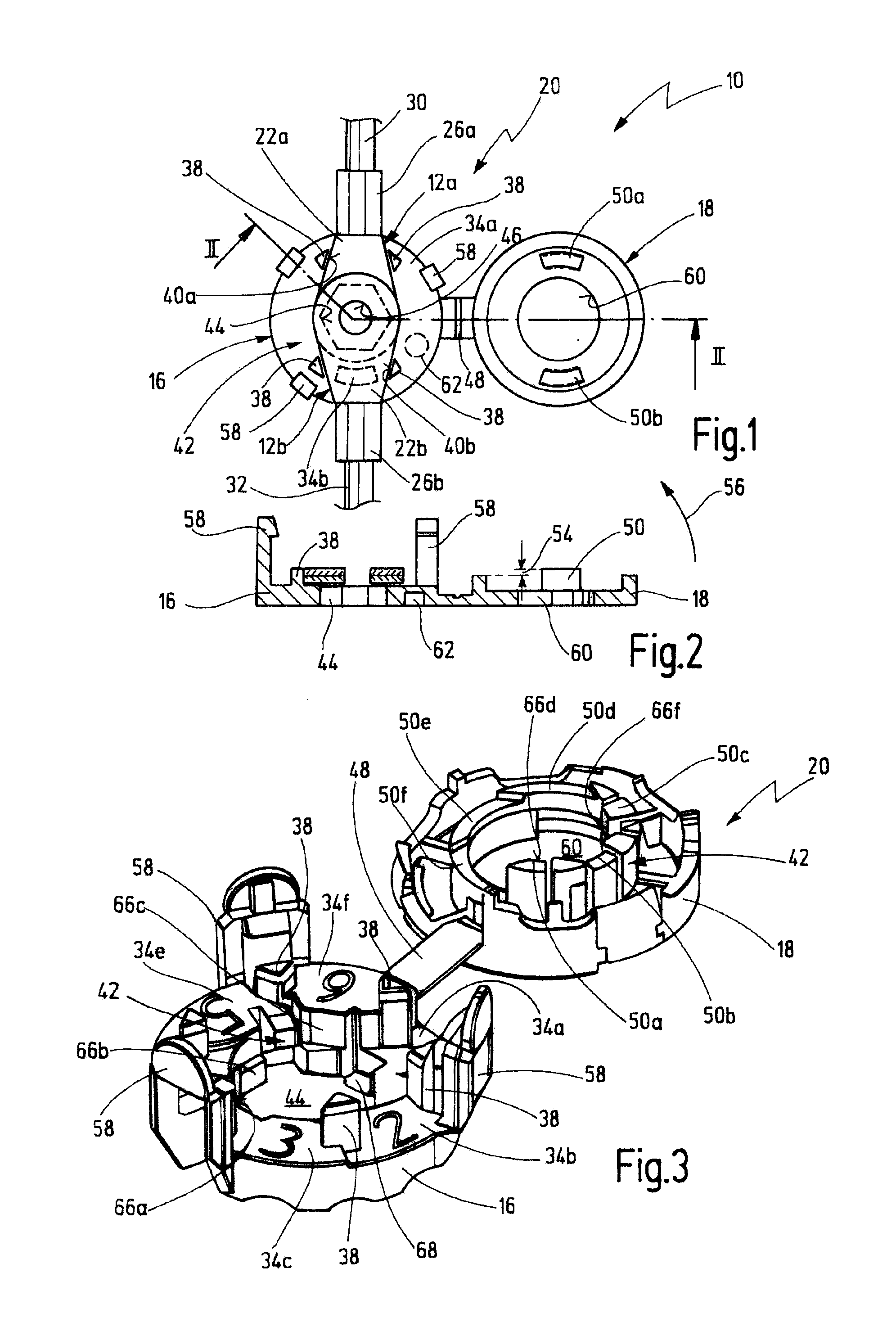
[0074]In FIGS. 1 and 2, a first embodiment of a holding arrangement according to the invention is generally denoted by 10.

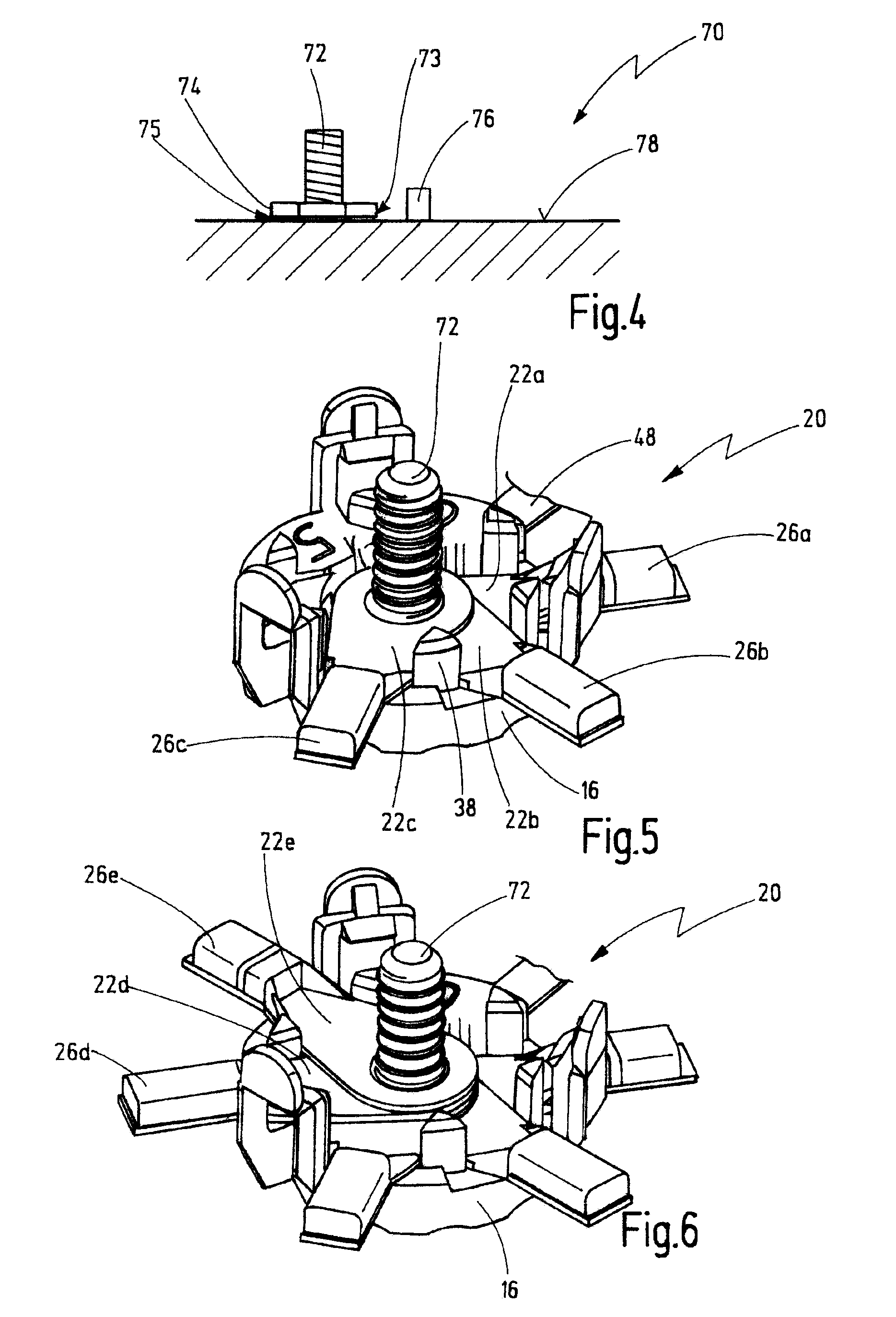
[0075]The holding arrangement serves the purpose of holding one or two cable lugs 12 (in the illustrated case two cable lugs) and has a base part 16 and a cover part 18. The base part 16 and the cover part 18 are shown in an open state, the cable lugs 12a, 12b having been inserted axially into the base part. The base part 16 and the cover part 18 each have an approximately circular outer circumference and, in the closed state, form a holding device 20, in which the inserted cable lugs 12 are held securely. The cable lugs 12a, 12b each have a metallic connection tongue 22a, 22b and a line section 26a, 26b, which adjoins the connection tongue. The line sections 26a, 26b are connected to a first electrical cable 30 and a second electrical cable 32, respectively. The cables 30, 32 can be part of a cable run.

[0076]The base part 16 has a first resting face 34a, on whic...


PUM

PropertyMeasurementUnit
Lengthaaaaaaaaaa
Thicknessaaaaaaaaaa
Heightaaaaaaaaaa

Abstract

The invention relates to a holding arrangement for at least two electrical connection elements, such as cable lugs, for example, which each have an electrical connection section and a line section, with a base part and a cover part, which can be connected to the base part to form the holding device, the connection sections being inserted axially one on top of the other in the holding device and being fixed axially, and the line sections extending in the radial direction from radial openings of the holding device, the radial openings being designed in such a way that the connection sections cannot be withdrawn from the radial openings, in addition an axial opening being formed on the base part and / or the cover part, via which axial opening electrical contact can be made with at least one connection section of the inserted connection sections, the holding device having centering means for centering the connection sections in the holding device, and the centering means acting on the outer circumference of the connection sections.

Description

CROSS-REFERENCE TO RELATED APPLICATIONS[0001]This application is a continuation of copending international patent application PCT / EP2009 / 000942 filed on Feb. 11, 2009 and designating the U.S., which claims priority of German patent application 10 2008 010 352.7 filed on Feb. 13, 2008. The entire contents of these applications are incorporated herein by reference.BACKGROUND OF THE INVENTION[0002]The present invention relates to a holding arrangement for at least two electrical connection elements, such as cable lugs, for example, which each have an electrical connection section and a line section.[0003]In addition, the present invention relates to a fitting apparatus for equipping such a holding arrangement and to a method for installing a ground contact between a ground bolt, which is attached to a mount such as a metal sheet, and at least one cable lug. The method for installing the ground contact should in this case preferably be carried out using a holding arrangement of the type...

Claims


Application Information

Patent Timeline
IPC IPC(8): H01R4/30H01R43/00
CPCH01R4/305Y10T29/49117H01R11/12
Inventor SENG, HANS-PETERREINDL, JOHANNSCHMIDT, THOMASNIEWOEHNER, HEINRICHGEBERT, ANDREAS
Owner NEWFREY
Learn More