Contactless respiration monitoring of a patient and optical sensor for a photoplethysmography measurement

a technology of optical sensor and patient, which is applied in the field of contactless respiration monitoring of a patient and optical sensor for a photoplethysmography measurement, can solve the problems of not being able to detect pulse wave and therefore not reaching the measurement location, unable to accurately measure all these parameters, and unable to meet the requirements of measurement equipment and time, so as to achieve reliable and fail-safe photoplethysmography measurement

Inactive Publication Date: 2011-03-03
KONINKLIJKE PHILIPS ELECTRONICS NV
View PDF18 Cites 23 Cited by
  • Summary
  • Abstract
  • Description
  • Claims
  • Application Information

AI Technical Summary

Benefits of technology

[0011]It is a first object of the invention to provide a possibility for a reliable and fail-safe photoplethysmography measurement.

Problems solved by technology

The problem especially encountered in reflective PPG setups is that the pressure, with which the skin is pressed onto the LED / photodiode combination, can be so high, that the blood vessels are actually clamped off, so that the pulse wave does not reach the measurement location and therefore cannot be detected.
Measuring all these parameters properly would require a substantial effort, both in terms of measurement equipment and time.
However, the practical circumstances in a hospital force the nurses to be as quick as possible with the spot-check measurements, because they have many other tasks to do, requiring more attention than the routine spot-checking.
Especially, respiratory action cannot be measured with conventional spot-checking setups yet.
However, attaching a sensor to the patient's chest is inconvenient and time-consuming.

Method used


Image

  • Contactless respiration monitoring of a patient and optical sensor for a photoplethysmography measurement
  • Contactless respiration monitoring of a patient and optical sensor for a photoplethysmography measurement
  • Contactless respiration monitoring of a patient and optical sensor for a photoplethysmography measurement

Examples


Embodiment Construction

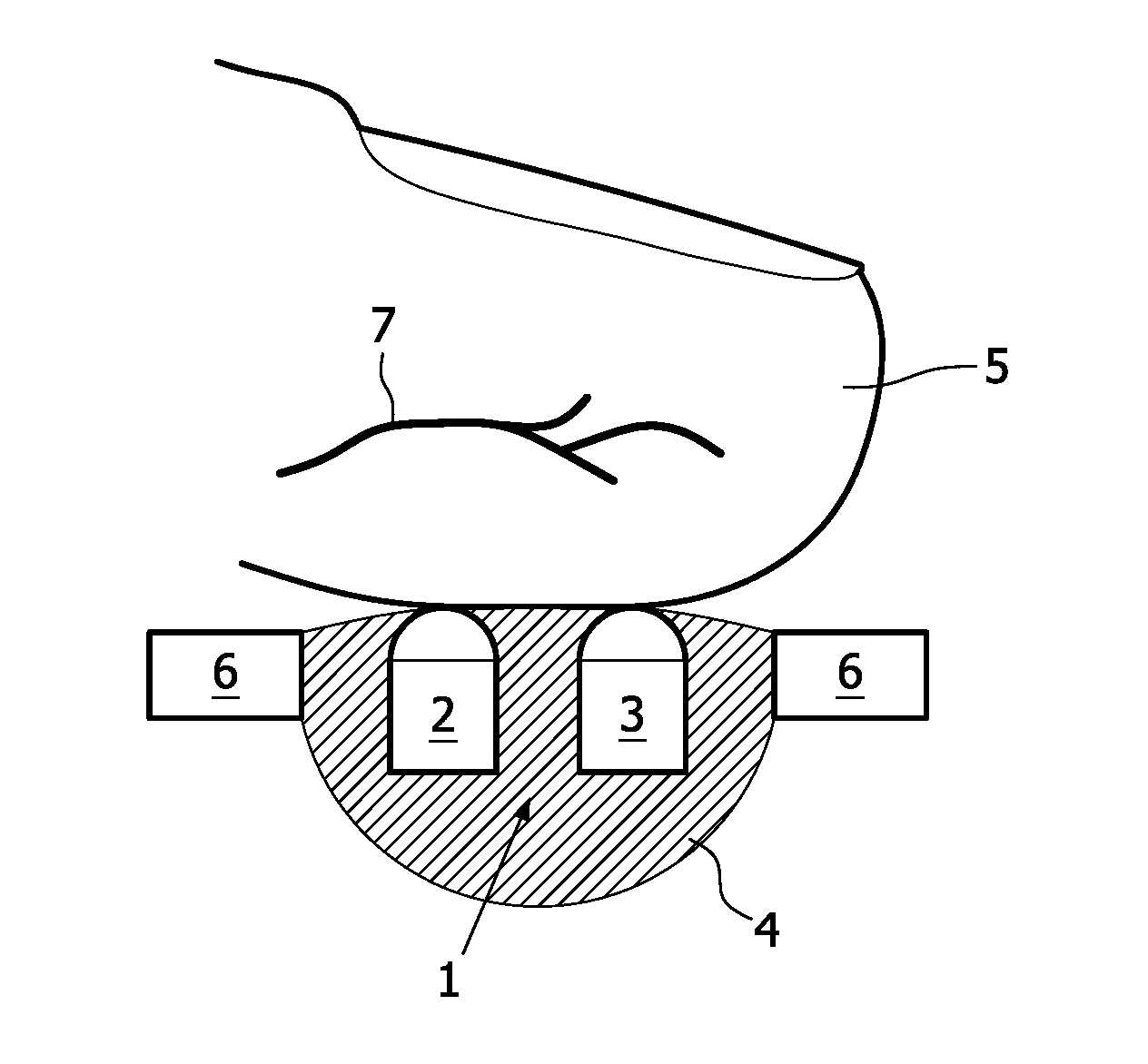
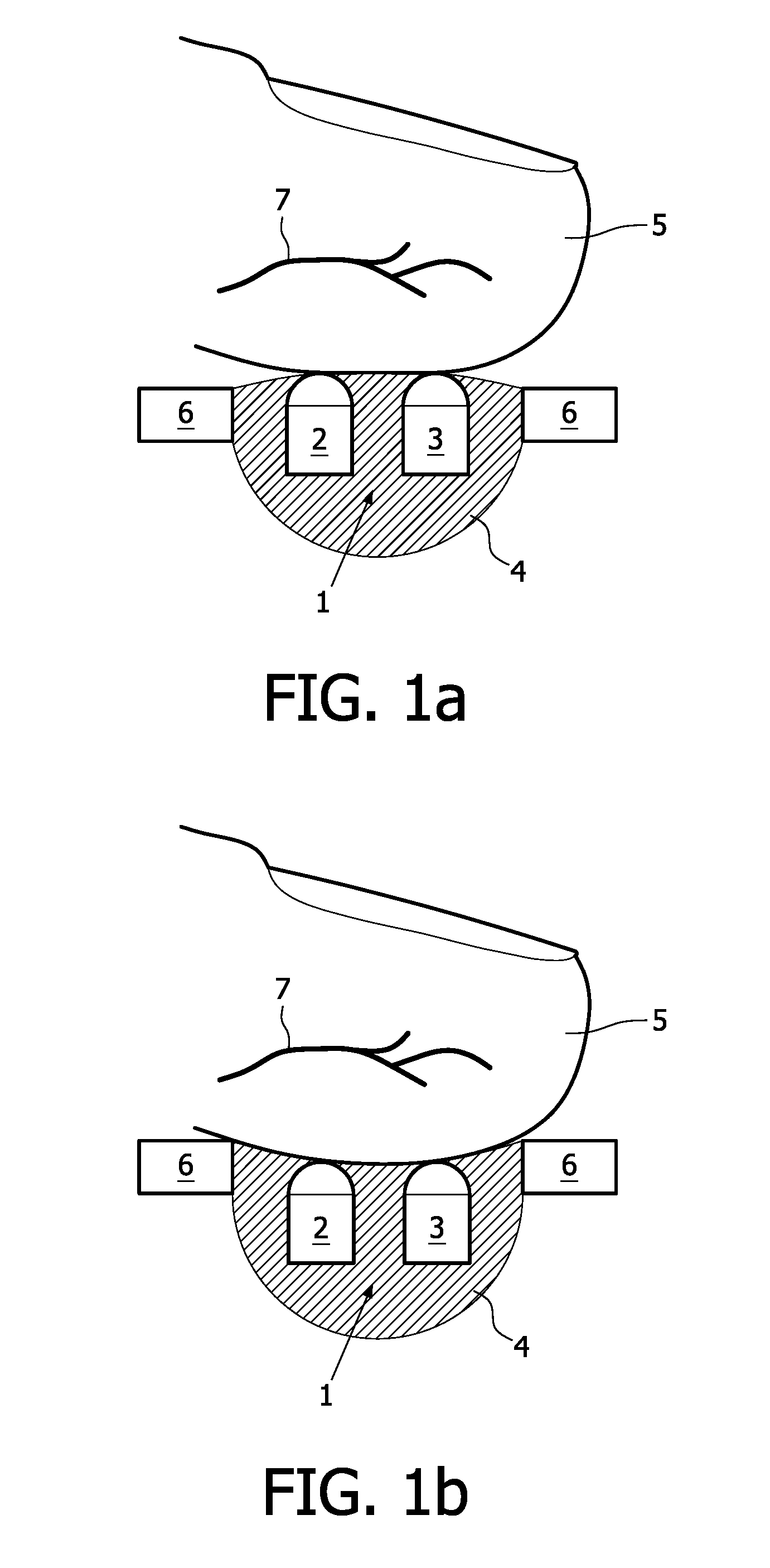
[0048]According to a first preferred embodiment of the invention, it is proposed to embed the light unit 1 of an optical sensor for a reflective photoplethysmography measurement with its light emitter 2 and its light detector 3, i.e. with its LED / photodiode combination, into an elastic material 4, e.g. silicone, that will give way to the finger pressure. An according reflective PPG setup can be seen from FIG. 1. There, it is shown that a patient's finger 5 is pressed on the elastic material 4 in which the light unit 1 with the light emitter 2 and the light detector 3 are provided. On its border area, the elastic material 4 is surrounded by a rigid carrier 6. In this way clamping of the finger capillaries 7 is avoided over a wide range of finger pressures.

[0049]As can be seen from FIG. 1, the elastic material 4 is deformed depending on the amount of finger pressure applied, and because of this deformation, clamping of the capillaries 7 is avoided, thereby allowing a valid PPG measure...


PUM


Abstract

The invention also relates to an optical sensor for a photoplethysmography measurement, comprising a light unit 1 with a light emitter 2 for emitting light into tissue of a patient 8 and/or a light detector 3 for detecting a part of the emitted light after interaction with the tissue, wherein the light unit is embedded in an elastic material 4. The invention further relates to a device for contactless respiration monitoring of a patient 8, comprising: a distance sensor for consecutively detecting the temporal distance variations relative to the patient's chest 12, preferably based on electromagnetic waves; and a calculating unit for determining the breathing activity based on the detected temporal distance variations. The invention is especially useful for providing a reliable and easy to use possibility for simultaneously monitoring respiration action, blood pressure and heart rate with a handheld device which can be used for spot-checking the vital parameters of patients in hospitals.

Description

FIELD OF THE INVENTION[0001]The invention relates to the field of contactless respiration monitoring of a patient and an optical sensor for a photoplethysmography measurement, and especially to a handheld device for simultaneously monitoring respiration action, blood pressure and heart rate which can preferably used for spot-checking the vital parameters of patients in hospitals.BACKGROUND OF THE INVENTION[0002]It is possible to detect the pulse wave arrival in a finger of a patient by means of an optical measurement: Typically, an infrared LED shines light into the finger and the amount of light that reaches a photodiode causes a photo current to flow through the diode. In the presence of the pulse wave, a large portion of the light is absorbed by the blood, i.e. the current through the photodiode is modulated accordingly. This technique is known as photoplethysmography (PPG).[0003]It is called “transmittive” PPG, if LED and photodiode are installed on opposite sides of the finger,...

Claims


Application Information

Patent Timeline
Patent Type & Authority Applications(United States)
IPC IPC(8): A61B5/1455A61B5/0205A61B5/08A61B5/332
CPCA61B5/0205A61B5/02125A61B5/02416A61B5/02438A61B5/0245G01S13/88A61B5/1135A61B5/14552A61B5/6826A61B5/6838A61B5/0816
Inventor PINTER, ROBERTMUEHLSTEFF, JENSSPEKOWIUS, GERHARDYU, DONGHAIDEVOT, SANDRINE MAGALI LAUREMUESCH, GUIDO JOSEFAUBERT, XAVIER LOUIS MARIE ANTOINE
Owner KONINKLIJKE PHILIPS ELECTRONICS NV
Why Eureka
Try Eureka