Turbine exhaust diffuser with region of reduced flow area and outer boundary gas flow

a technology of exhaust diffuser and turbine engine, which is applied in the direction of hot gas positive displacement engine plants, engine components, machines/engines, etc., can solve the problems of long hubs, increased cost and material cracking risk, and complicated engine design

Inactive Publication Date: 2011-03-10
SIEMENS ENERGY INC
View PDF25 Cites 27 Cited by
  • Summary
  • Abstract
  • Description
  • Claims
  • Application Information

AI Technical Summary

Benefits of technology

[0010]In accordance with an aspect of the invention, an exhaust diffuser for a turbine engine may be provided comprising an inner boundary defined at least by a hub. The hub may include an upstream end and a downstream end. An outer boundary may be defined by a diffuser shell, the outer boundary being radially spaced from the inner boundary so that a flow path is defined therebetween. The outer boundary comprises a radially inwardly extending region in which the outer boundary extends radially inwardly toward the inner boundary. The radially inwardly extending region begins at a point that is one of substantially aligned and proximately upstream of the downstream end of the hub, whereby the outer boundary directs at least a portion of an exhaust flow in the diffuser toward the hub. At least one gas jet is provided including a jet exit located on the outer boundary. The jet exit may discharge a flow of gas downstream substantially parallel to an inner surface of the outer boundary to effect a radially outward flow of a portion of the exh

Problems solved by technology

However, a long hub presents a disadvantage in that it can make the engine design more complicated and expensive.
These support struts 36 can increase cost and the risk of material cracking due to thermal mismatch between inner and outer flowpath parts or vibratory loads.
Further, lo

Method used


Image

  • Turbine exhaust diffuser with region of reduced flow area and outer boundary gas flow
  • Turbine exhaust diffuser with region of reduced flow area and outer boundary gas flow
  • Turbine exhaust diffuser with region of reduced flow area and outer boundary gas flow

Examples


Embodiment Construction

[0020]In the following detailed description of the preferred embodiment, reference is made to the accompanying drawings that form a part hereof, and in which is shown by way of illustration, and not by way of limitation, a specific preferred embodiment in which the invention may be practiced. It is to be understood that other embodiments may be utilized and that changes may be made without departing from the spirit and scope of the present invention.

[0021]Embodiments of the invention are directed to an exhaust diffuser system, which can increase the power and efficiency of a turbine engine. Aspects of the invention will be explained in connection with various possible configurations, but the detailed description is intended only as exemplary. Embodiments of the invention are shown in FIGS. 2-6 and 6A, but the present invention is not limited to the illustrated structure or application.

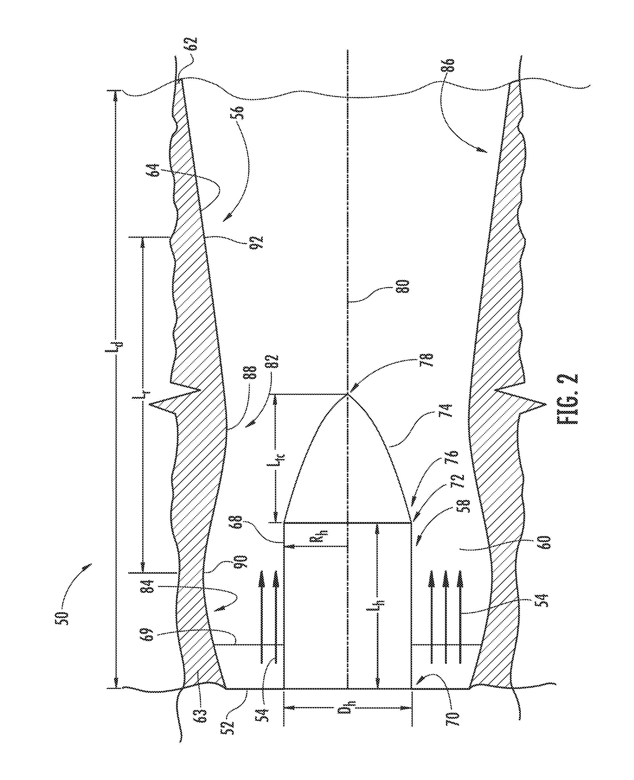
[0022]FIG. 2 shows a portion of the exhaust diffuser section 50 of a turbine engine configured in a...


PUM


Abstract

An exhaust diffuser system and method for a turbine engine. The outer boundary may include a region in which the outer boundary extends radially inwardly toward the hub structure and may direct at least a portion of an exhaust flow in the diffuser toward the hub structure. At least one gas jet is provided including a jet exit located on the outer boundary. The jet exit may discharge a flow of gas downstream substantially parallel to an inner surface of the outer boundary to direct a portion of the exhaust flow in the diffuser toward the outer boundary to effect a radially outward flow of at least a portion of the exhaust gas flow toward the outer boundary to balance an aerodynamic load between the outer and inner boundaries.

Description

CROSS-REFERENCE TO RELATED APPLICATION[0001]This application is A CONTINUATION-IN-PART APPLICATION of and claims priority to U.S. patent application Ser. No. 12 / 476,302, (Attorney Docket No. 2009P07383US), filed on Jun. 2, 2009, entitled “TURBINE EXHAUST DIFFUSER FLOW PATH WITH REGION OF REDUCED TOTAL FLOW AREA,” the entire disclosure of which is incorporated by reference herein.STATEMENT REGARDING FEDERALLY SPONSORED DEVELOPMENT[0002]Development for this invention was supported in part by Contract No. DE-FC26-05NT42644, awarded by the United States Department of Energy. Accordingly, the United States Government may have certain rights in this invention.FIELD OF THE INVENTION[0003]The invention relates in general to turbine engines and, more particularly, to exhaust diffusers for turbine engines.BACKGROUND OF THE INVENTION[0004]Referring to FIG. 1, a turbine engine 10 generally includes a compressor section 12, a combustor section 14, a turbine section 16 and an exhaust section 18. ...

Claims


Application Information

Patent Timeline
IPC IPC(8): F02C7/08
CPCF01D25/305F01D25/30
Inventor OROSA, JOHN
Owner SIEMENS ENERGY INC
Why Eureka
Try Eureka