Shock absorbing device

a technology damping force, which is applied in the direction of shock absorption device, mechanical equipment, transportation and packaging, etc., can solve the problems of reducing the inability to realize a reduction in the generated damping force, and the conventional shock absorption device, so as to improve the passenger comfort of the vehicle, reduce the damping force relative to the speed of the piston, and reduce the damping force

Active Publication Date: 2011-03-10
KYB CORP
View PDF11 Cites 42 Cited by
  • Summary
  • Abstract
  • Description
  • Claims
  • Application Information

AI Technical Summary

Benefits of technology

[0013]In the shock absorbing device according to this invention, a gradient of a damping force relative to a piston speed can be reduced even in situations where the piston speed is high, such as when the vehicle travels over a projection, and therefore the damping force can be reduced reliably. Hence, in contrast to a conventional shock absorbing device, in which the damping force remains high such that vibration transfer from the axle to the vehicle body cannot be suppressed favorably, an improvement in the passenger comfort of the vehicle can be achieved.
[0014]Further, in the shock absorbing device according to this invention, when the piston speed is low, the damping force can be increased in response to low-frequency vibration and reduced in response to high-frequency vibration, and thus, a damping force of an appropriate magnitude can be generated in accordance with the frequency. As a result, the attitude of the vehicle can be stabilized when the vehicle turns, thereby preventing passengers from feeling anxious, and vibration transfer from the axle side to the vehicle body side can be suppressed, thereby improving the passenger comfort of the vehicle.

Problems solved by technology

However, a conventional shock absorbing device has the following problems.
Therefore, in a case where the piston operates at an extremely high speed, for example when the vehicle travels over a projection or the like, a flow passage resistance in the orifice may greatly exceed a flow passage resistance in the first flow passage, and as a result, the flow rate through the first flow passage may greatly exceed the flow rate through the second flow passage, making it impossible to realize a reduction in the generated damping force.
Hence, when the piston speed is high in a conventional shock absorbing device, the damping force may remain high, and as a result, vibration transfer from an axle side to a vehicle body side may be suppressed less favorably, leading to a reduction in the passenger comfort of the vehicle.

Method used


Image

  • Shock absorbing device
  • Shock absorbing device
  • Shock absorbing device

Examples


Embodiment Construction

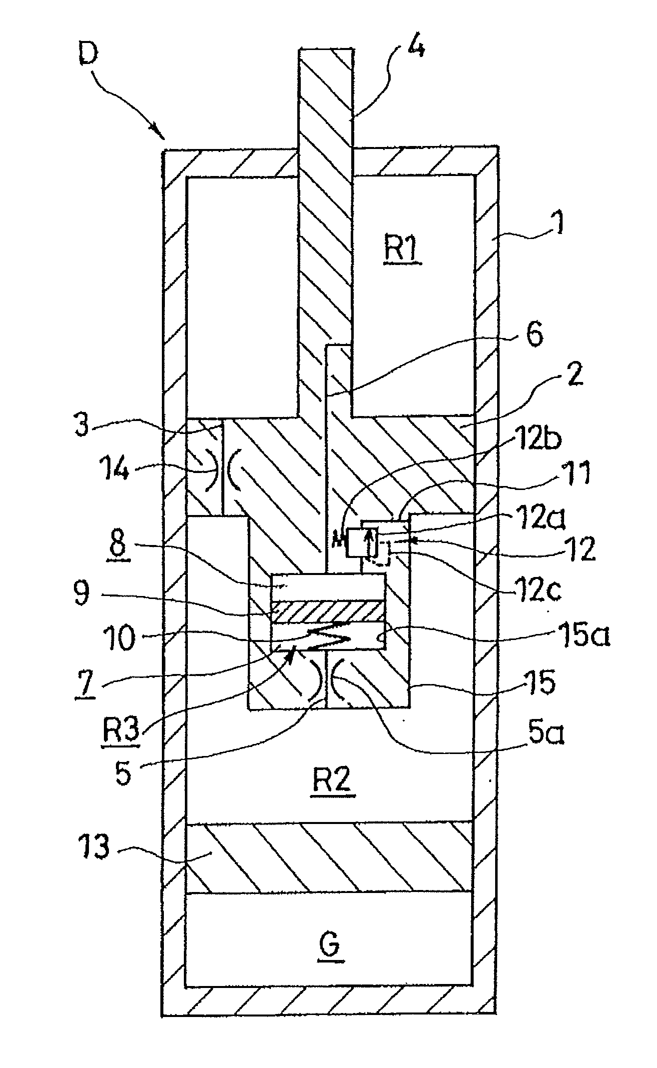
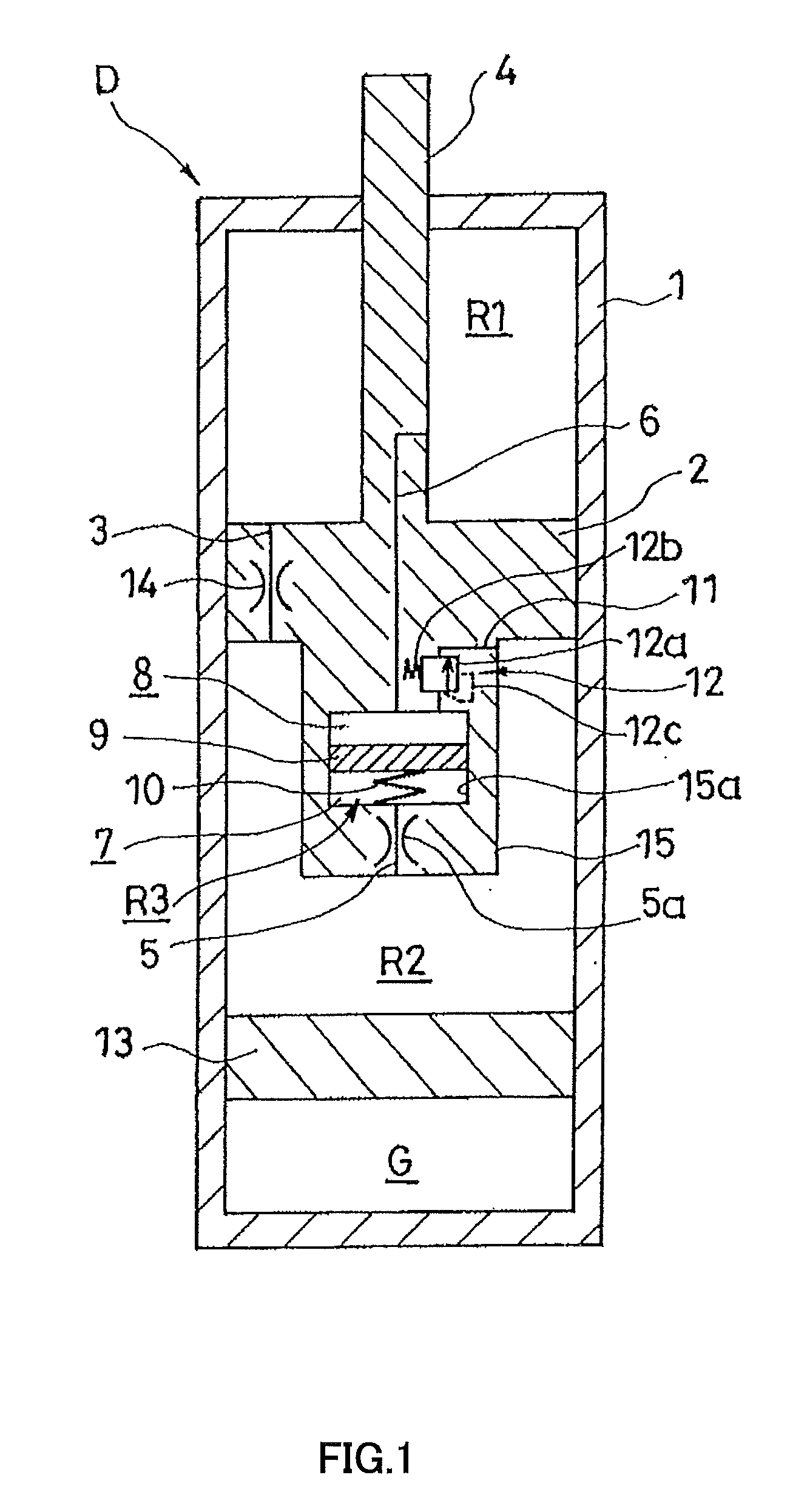
[0028]This invention will be described below on the basis of the figures. As shown in FIG. 1, a shock absorbing device D according to this invention is constituted by a cylinder 1, a piston 2 that is inserted into the cylinder 1 to be free to slide and serves as a partition wall member that partitions the interior of the cylinder 1 into two operating chambers, namely an upper chamber R1 and a lower chamber R2, a passage 3 that connects the upper chamber R1 and the lower chamber R2, a pressure chamber R3, a free piston 9 that is inserted into the pressure chamber R3 to be free to slide and partitions the pressure chamber R3 into a one chamber 7 that communicates with the lower chamber R2 via a one side flow passage 5 and an other chamber 8 that communicates with the upper chamber R1 via an other side flow passage 6, a spring element 10 that generates a biasing force to suppress displacement of the free piston 9 relative to the pressure chamber R3, a bypass flow passage 11 that connec...


PUM


Abstract

A shock absorbing device includes a cylinder. A partition wall member is inserted into the cylinder to be free to slide and partitions an interior of the cylinder into two operating chambers. A passage connects the two operating chambers. A free piston is inserted into a pressure chamber to be free to slide and partitions the pressure chamber into one chamber that communicates with one operating chamber via a one side flow passage and another chamber that communicates with the other operating chamber via another side flow passage. A spring element generates a biasing force for suppressing displacement of the free piston relative to the pressure chamber. One or both of a bypass flow passage that connects the other chamber and the one operating chamber and a bypass flow passage that connects the one chamber and the other operating chamber is provided. A relief valve is provided in the bypass flow passage.

Description

TECHNICAL FIELD[0001]This invention relates to a shock absorbing device.BACKGROUND ART[0002]A shock absorbing device described in JP2006-336816A and JP2007-78004A includes a cylinder, a piston that is inserted into the cylinder to be free to slide and partitions the interior of the cylinder into an upper chamber and a lower chamber, a first flow passage provided in the piston to connect the upper chamber and the lower chamber, a second flow passage that opens onto a side portion of a piston rod from a tip end thereof and connects the upper chamber and the lower chamber, a housing that is attached to the tip end of the piston rod and includes a pressure chamber connected to a midway point of the second flow passage, a free piston that is inserted into the pressure chamber to be free to slide and partitions the pressure chamber into a one chamber and the other chamber, and a coil spring that biases the free piston. Thus, the one chamber of the pressure chamber communicates with the lo...

Claims


Application Information

Patent Timeline
Patent Type & Authority Applications(United States)
IPC IPC(8): F16F9/19F16F9/34B60G17/08
CPCF16F9/5126F16F9/516
Inventor TERAOKA, TAKASHIMASAMURA, TATSUYA
Owner KYB CORP
Why Eureka
Try Eureka