Single Cylinder Type Hydraulic Shock Absorber for Vehicle

a single cylinder type, hydraulic shock absorber technology, applied in the direction of shock absorbers, mechanical equipment, transportation and packaging, etc., can solve the problems of broken lines, inability to easily flow working oil from the contraction side oil chamber into the expansion side oil chamber, and inability to keep the pressure increase in the gas chamber, so as to improve the passenger comfort of the vehicle, prevent the effect of the contraction side from causing the vibration of the vehicle body and suppress the vibration sufficiently

Inactive Publication Date: 2009-04-30
KYB CORP
View PDF14 Cites 10 Cited by
  • Summary
  • Abstract
  • Description
  • Claims
  • Application Information

AI Technical Summary

Benefits of technology

[0009]This invention has been designed in consideration of the problems described above, and it is an object thereof to provide a single cylinder type hydraulic shock absorber which is capable of improving the passenger comfort of a vehicle by exhibiting a favorable damping characteristic even when a piston speed is high.
[0011]According to this invention, during a contraction stroke of the shock absorber, the free piston is biased not only by an increase in the internal pressure of the gas chamber, but also by the elastic member, and therefore the interior of the fluid chamber is greatly pressurized. Hence, a situation in which the free piston moves in parallel with the piston is avoided even when the piston speed is high. Accordingly, the damping force on the contraction side is prevented from peaking, and as a result, vibration in the vehicle body can be suppressed sufficiently, enabling an improvement in the passenger comfort of the vehicle.
[0012]Furthermore, by avoiding a situation in which the free piston moves in parallel with the piston, the internal pressure of the expansion side pressure chamber is prevented from falling below the outside air pressure. As a result, outside air is prevented from being sucked into the cylinder through a gap between the sealing member and the rod, thereby eliminating the danger of aeration, adiabatic compression, and so on.
[0013]Further, the spring constant of the elastic member increases during contraction, and thus the elastic member acts to supplement the biasing force that is applied to the free piston by the internal pressure of the gas chamber. Therefore, the internal pressure of the gas chamber does not need to be set high in advance, and as a result, the passenger comfort of the vehicle is not impaired.

Problems solved by technology

When the piston speed is high during a contraction stroke in a conventional hydraulic shock absorber, a pressure increase in the gas chamber may not be able to keep up with a pressure increase in a contraction side oil chamber partitioned by the free piston, and as a result, the internal pressure of the contraction side oil chamber may become equal to or greater than the internal pressure of the gas chamber.
In such a case, the free piston moves in parallel with the piston such that the volume of the contraction side oil chamber does not vary, and therefore the working oil in the contraction side oil chamber cannot flow easily into an expansion side oil chamber.
Therefore, the damping characteristic shown by the broken line in FIG. 5, which is required to suppress vibration in the vehicle body, cannot be realized.
Further, when the working oil does not flow into the expansion side oil chamber and the volume thereof simply expands, the internal pressure of the expansion side oil chamber may fall below the outside air pressure, causing outside air to be sucked into the cylinder through a gap between the rod and a sealing member provided between the rod and the cylinder.
In so doing, however, the internal pressure of the oil chambers in the cylinder becomes higher than necessary, thereby impairing the passenger comfort of the vehicle.
Moreover, the internal pressure of the oil chambers acts excessively on the sealing member, and as a result, the rod is prevented from moving smoothly, leading to a reduction in the life of the sealing member.

Method used


Image

  • Single Cylinder Type Hydraulic Shock Absorber for Vehicle
  • Single Cylinder Type Hydraulic Shock Absorber for Vehicle
  • Single Cylinder Type Hydraulic Shock Absorber for Vehicle

Examples


first embodiment

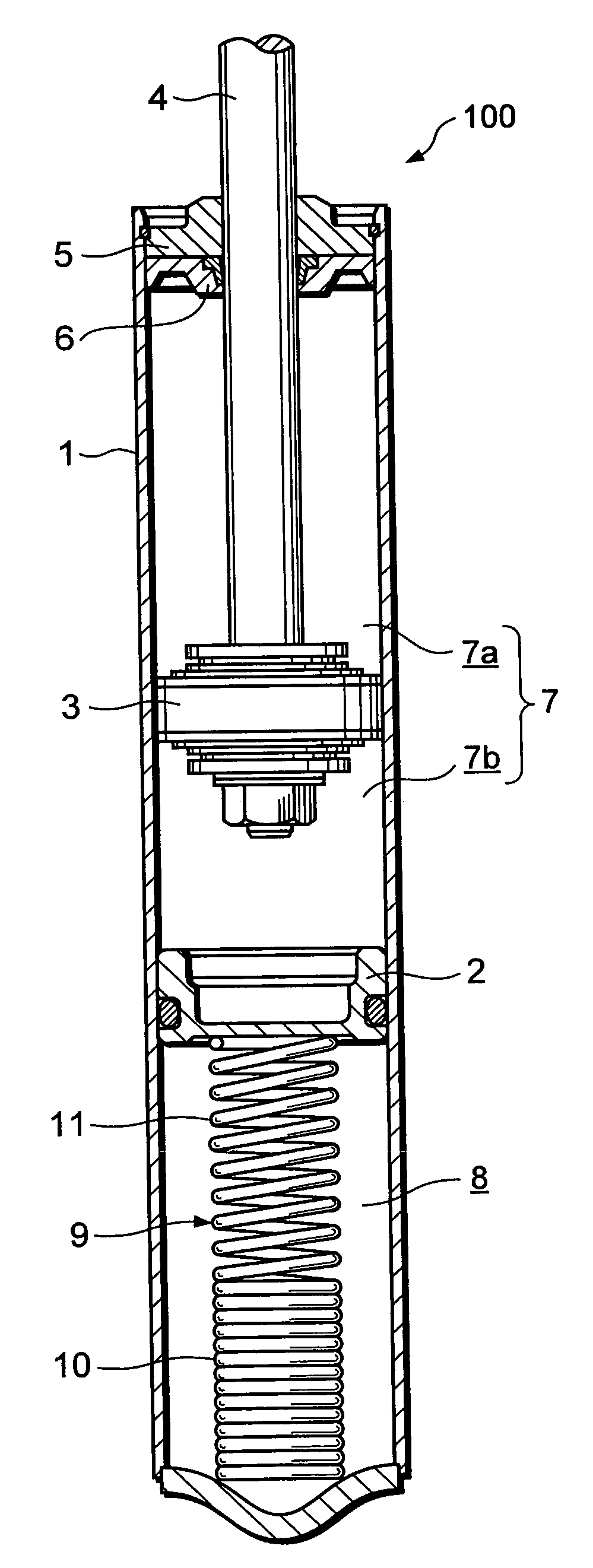
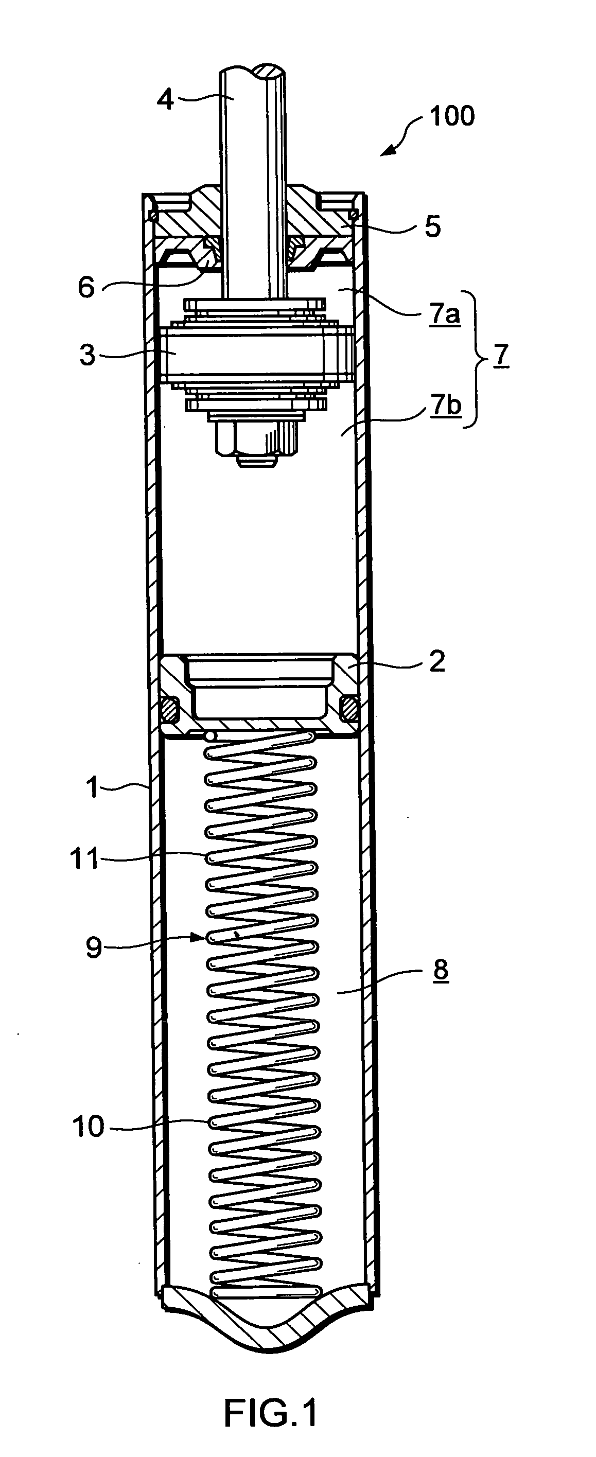
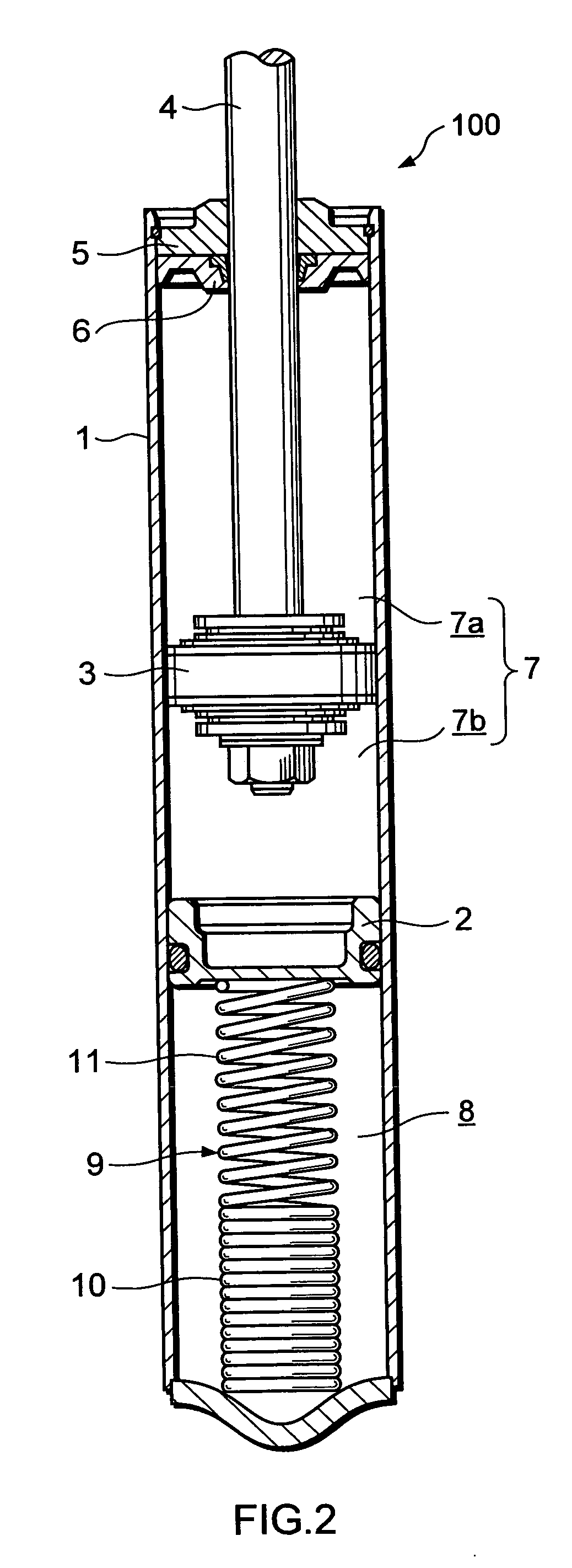
[0020]First, referring to FIGS. 1 to 3, a single cylinder type hydraulic shock absorber for a vehicle 100 according to a first embodiment of this invention will be described.

[0021]The single cylinder type hydraulic shock absorber for a vehicle (to be referred to as a “shock absorber” hereafter) 100 is interposed between a vehicle body and an axle of a vehicle to suppress vibration in the vehicle body, and as shown in FIG. 1, comprises a cylinder 1, a free piston 2 that is inserted slidably into the cylinder 1 and delimits a fluid chamber 7 and a gas chamber 8 in the cylinder 1, a piston 3 that is inserted slidably into the cylinder 1 and delimits the fluid chamber 7 into two pressure chambers 7a, 7b, and a rod 4, one end of which is connected to the piston 3 and another end of which extends to the exterior of the cylinder 1.

[0022]A fluid such as working oil is charged into the expansion side pressure chamber 7a and the contraction side pressure chamber 7b. Further, a pressurized gas...

second embodiment

[0049]Next, referring to FIG. 4, a single cylinder type hydraulic shock absorber for a vehicle 200 according to a second embodiment of this invention will be described. It should be noted that identical members to those of the shock absorber 100 according to the first embodiment described above have been allocated identical reference symbols, and description thereof has been omitted.

[0050]The shock absorber 200 differs from the shock absorber 100 of the first embodiment in the constitution of the elastic member. The following description will focus on this difference.

[0051]An elastic member 12 of the shock absorber 200 is made of synthetic resin, and as shown in FIG. 4, comprises a base portion 15 that is fitted to the inner periphery of the cylinder 1, and a biasing portion 16 that stands upright from the base portion 15 and contacts the end portion of the free piston 2.

[0052]The biasing portion 16 comprises a small spring constant site 16a on its tip end side and a large spring co...


PUM


Abstract

A single cylinder type hydraulic shock absorber for a vehicle (100) includes a cylinder (1), a free piston (2) that is inserted slidably into the cylinder (1) and delimits a fluid chamber (7) and a gas chamber (8) in the cylinder (1), a piston (3) that is inserted slidably into the cylinder (1) and delimits the fluid chamber (7) into two pressure chambers (7a, 7b), a rod (4), one end of which is connected to the piston (3), and an elastic member (9) that is accommodated in the gas chamber (8) and biases the free piston (2) in the direction of the fluid chamber (7). The elastic member (9) is set such that a spring constant thereof increases during contraction.

Description

TECHNICAL FIELD[0001]This invention relates to an improvement in a single cylinder type hydraulic shock absorber for a vehicle.BACKGROUND ART[0002]In a known conventional single cylinder type hydraulic shock absorber that is interposed between a vehicle body and an axle of a vehicle in order to suppress vibration in the vehicle body, a piston that contacts an inner peripheral surface of a cylinder slidingly is attached fixedly to a tip end portion of a rod, and an oil chamber and a gas chamber are delineated by fitting a free piston slidingly within the cylinder (see JP08-159199).[0003]A passage that connects two oil chambers delineated by the piston is provided in the piston, and an orifice or the like that applies resistance to a flow of working oil passing through the passage is interposed in the piston. When the piston slides within the cylinder, the working oil travels between the oil chambers through the passage. Thus, the hydraulic shock absorber generates a damping force.[00...

Claims


Application Information

Patent Timeline
Patent Type & Authority Applications(United States)
IPC IPC(8): F16F9/32
CPCB60G13/08F16F9/585F16F9/061B60G2202/24F16F9/32
Inventor OTA, AKIHISA
Owner KYB CORP
Why Eureka
Try Eureka