
Damping valve for shock absorber

a technology for shock absorbers and valves, which is applied in the direction of shock absorbers, magnetic springs, vibration dampers, etc., can solve the problems of increasing the overall length of the piston portion and the difficulty of ensuring the stroke length of the shock absorber, so as to improve the passenger comfort of the vehicle and secure the effect of easy operation

Inactive Publication Date: 2013-05-02
KYB CORP
View PDF2 Cites 6 Cited by
  • Summary
  • Abstract
  • Description
  • Claims
  • Application Information

AI Technical Summary

Benefits of technology

The technical effect of this patent text is to provide a damping valve that can make sure that the vehicle's shock absorber has enough space to move and that it is comfortable for passengers.

Problems solved by technology

In the damping valve described in JP09-291961A, however, the coil spring is required, and in order to secure a lift amount of the leaf valve, an overall length of a piston portion must be increased, making it difficult to secure a stroke length of the shock absorber.

Method used


Image

  • Damping valve for shock absorber
  • Damping valve for shock absorber
  • Damping valve for shock absorber

Examples


first embodiment

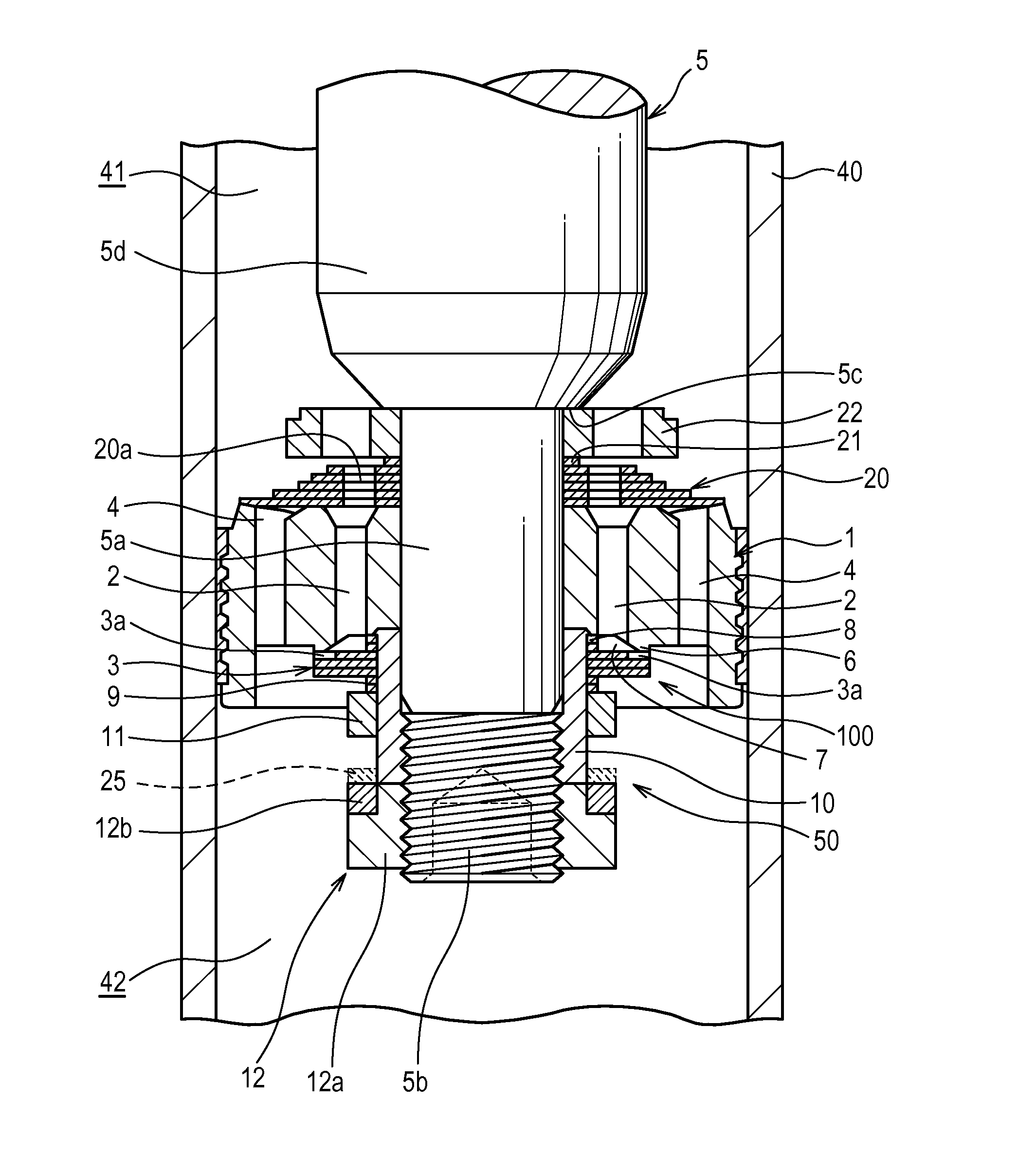
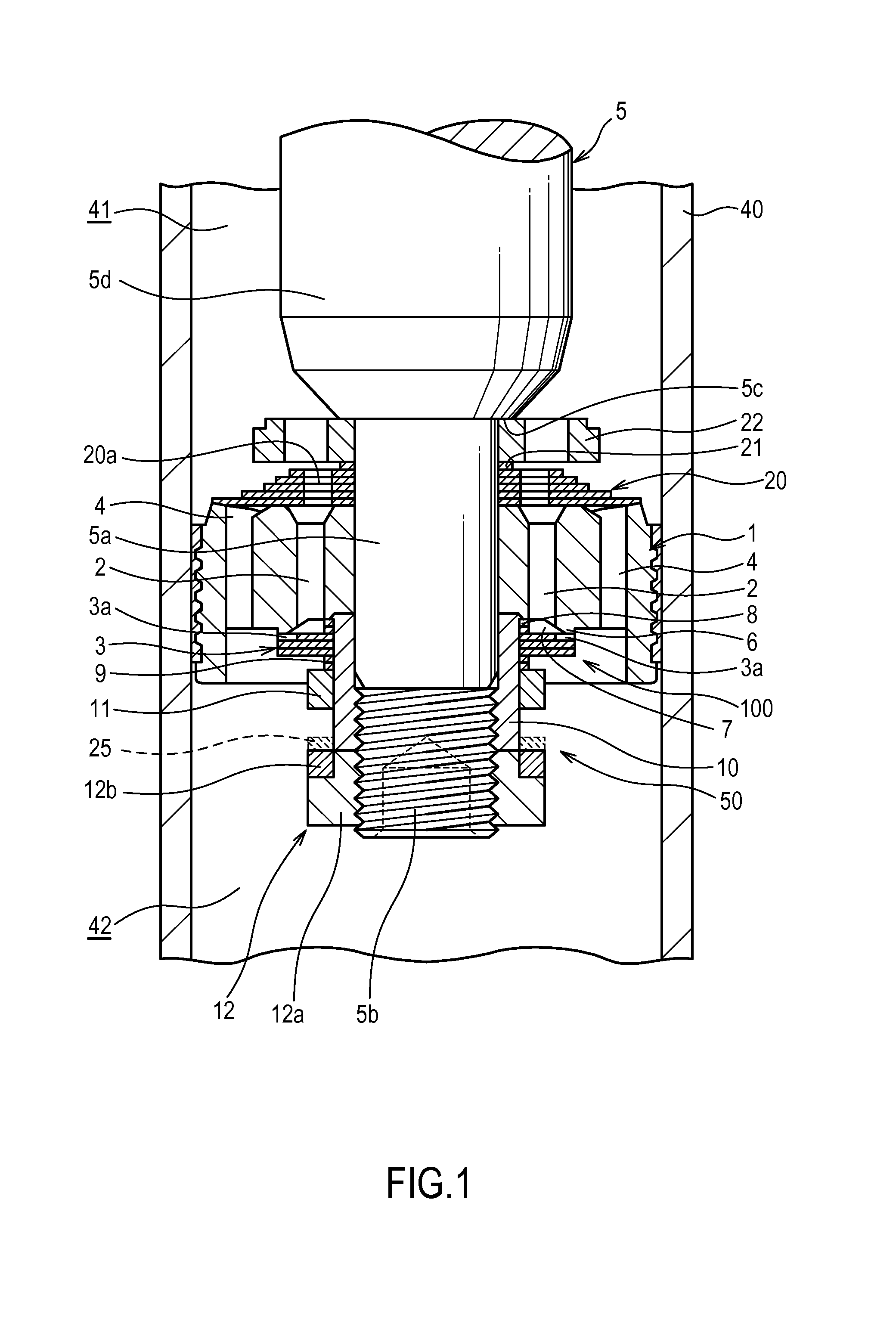
[0014]Referring to FIG. 1, a damping valve 100 for a shock absorber according to a first embodiment of this invention will be described.

[0015]The damping valve 100 is interposed between a vehicle body and an axle of a vehicle in order to suppress vibration of the vehicle body, and provided on a piston of a shock absorber. In this embodiment, a case in which the damping valve 100 is an expansion side damping valve that generates expansion side damping force by applying resistance to working oil (a working fluid) when the shock absorber performs an expansion operation will be described.

[0016]The damping valve 100 includes a piston 1 serving as a valve disc that delimits an interior of a cylinder 40 filled with working oil, a port 2 provided in the piston 1, an annular leaf valve 3 that is laminated onto the piston 1 in order to open and close the port 2, and a biasing mechanism 50 that biases the leaf valve 3 in a direction for closing the port 2.

[0017]The piston 1 moves so as to slid...

second embodiment

[0064]Next, referring to FIG. 4, a damping valve 200 for a shock absorber according to a second embodiment of this invention will be described.

[0065]The following description focuses on points that differ from the first embodiment. Accordingly, identical configurations to the damping valve 100 of the first embodiment have been allocated identical reference symbols, and description thereof has been omitted.

[0066]The damping valve 200 differs from the damping valve 100 according to the first embodiment in that the piston 1 is formed from a magnetic body. Further, the damping valve 200 is not provided with the magnetism generating member 12, and a piston nut 60 serving as a fixing member formed from a non-magnetic body is screwed to the screw portion 5b on the small diameter portion 5a of the piston rod 5.

[0067]In the second embodiment, the biasing mechanism 50 includes the shaft member 10, the moving magnet 11, and the magnetic body piston 1, and uses the attractive force with which t...


PUM


Abstract

The damping valve for a shock absorber includes a valve disc that delimits a cylinder interior filled with a working fluid, a port connects fluid chambers delimited by the valve disc, an leaf valve that is laminated onto the valve disc and is capable of moving in an axial direction of the valve disc so as to open and close the port in accordance with a differential pressure between the fluid chambers, and a biasing mechanism that biases the leaf valve in a direction for closing the port, wherein the biasing mechanism includes a shaft member constituted by a non-magnetic body, the leaf valve being disposed to be free to slide on an outer periphery of the shaft member; and a moving magnet that uses a magnetic force thereof to bias the leaf valve toward the valve disc.

Description

TECHNICAL FIELD[0001]This invention relates to a damping valve for a shock absorber.BACKGROUND ART[0002]In an example of a known conventional damping valve for a shock absorber, an annular leaf valve is laminated onto an outlet end of a port provided in a piston portion of the shock absorber so that the port is opened and closed by the leaf valve.[0003]In particular, with a damping valve in which an inner peripheral side of the leaf valve is supported fixedly and the port is opened and closed by causing an outer peripheral side to bend, a damping force generated when a piston speed is in a medium / high speed region may become excessive, thereby impairing passenger comfort in a vehicle. To solve this problem, JP09-291961A discloses a damping valve for a hydraulic shock absorber in which the inner peripheral side of the leaf valve is not supported fixedly, and instead, the inner periphery of the leaf valve is caused to slide against an outer periphery of a piston nut and a back surface...

Claims


Application Information

Patent Timeline
Patent Type & Authority Applications(United States)
IPC IPC(8): F16F9/348
CPCF16F6/00F16F9/3484F16F9/3485F16F9/3488F16F9/464F16F9/512F16F2222/06
Inventor MURATA, TAKAO
Owner KYB CORP
Learn More