Suspension apparatus

a suspension apparatus and suspension technology, applied in mechanical apparatus, shock absorbers, transportation and packaging, etc., can solve the problem of increasing complexity in the configuration of the suspension apparatus, and achieve the effect of improving passenger comfort and simple configuration

Active Publication Date: 2017-03-14
TOYOTA JIDOSHA KK
View PDF15 Cites 0 Cited by
  • Summary
  • Abstract
  • Description
  • Claims
  • Application Information

AI Technical Summary

Benefits of technology

[0006]The invention provides a suspension apparatus having a simple configuration, with which a further improvement in passenger comfort can be achieved during vehicle travel.
[0015]With the suspension apparatus according to the invention, which has a simple configuration including the expansion side friction member and the contraction side friction member, a further improvement in passenger comfort can be achieved during vehicle travel.

Problems solved by technology

In the suspension apparatus described above, fine control of an actuator and so on are required to vary the friction generated in the damping mechanism during damping of the periodic vibration of the elastic body, and therefore a configuration of the suspension apparatus tends to increase in complexity.

Method used


Image

  • Suspension apparatus
  • Suspension apparatus
  • Suspension apparatus

Examples


first embodiment

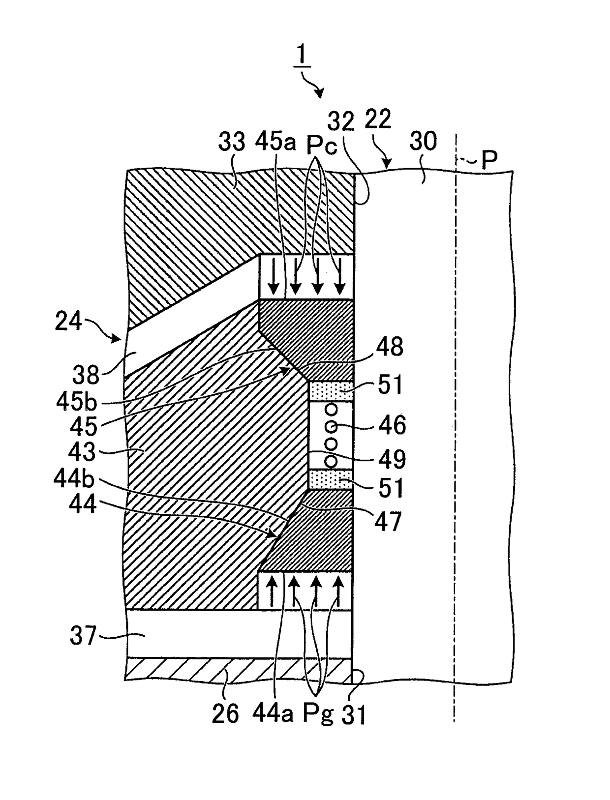
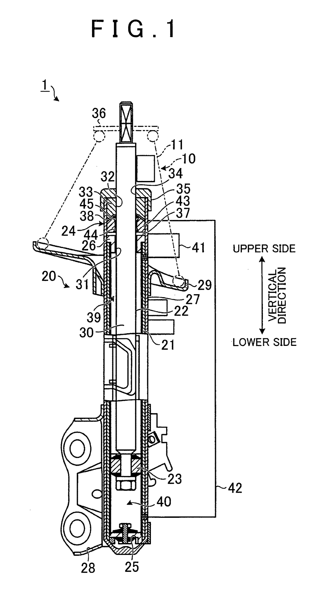
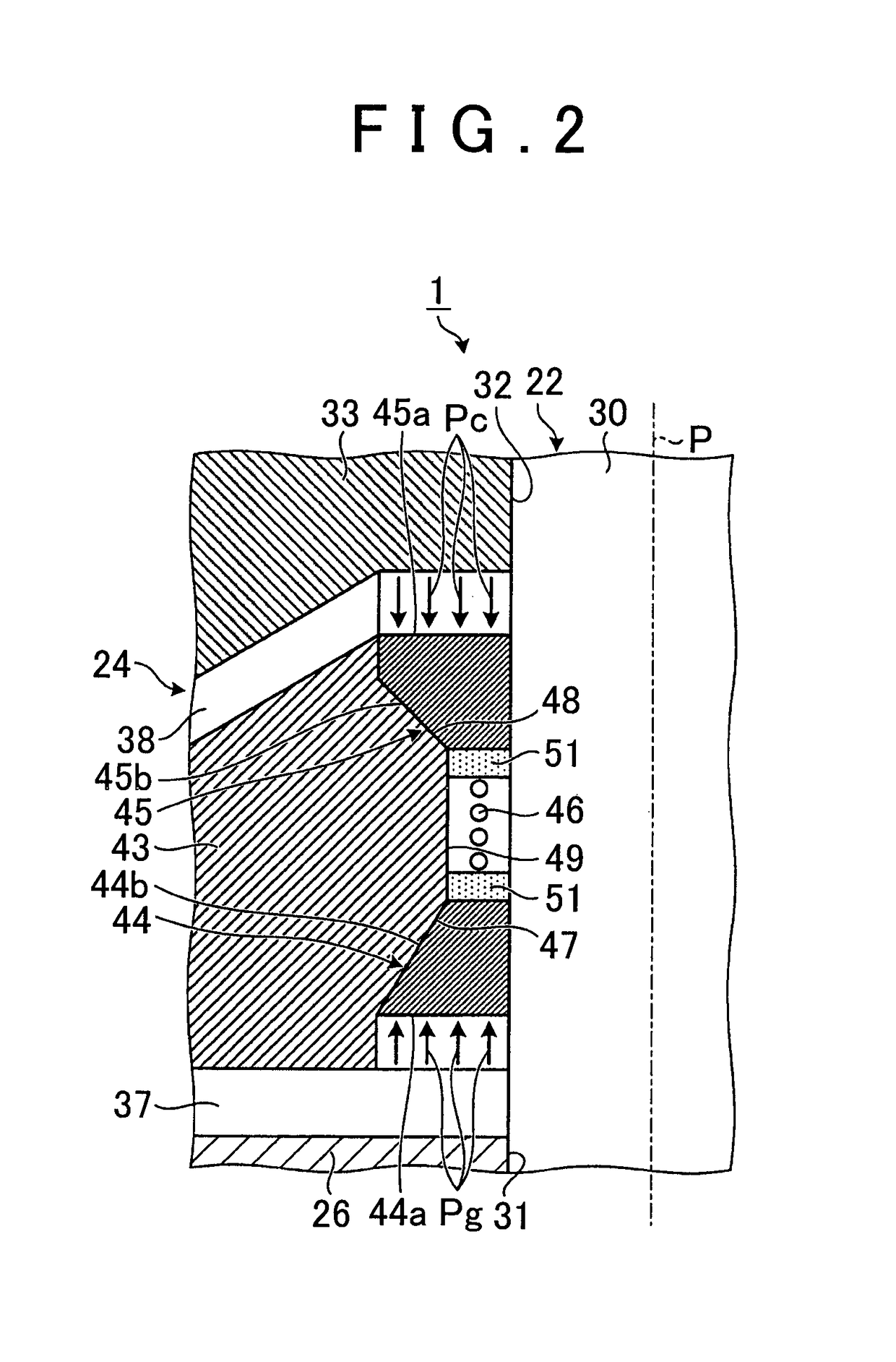
[0027]A suspension apparatus according to a first embodiment of the invention will now be described on the basis of FIGS. 1 to 4. FIG. 1 is a longitudinal sectional view showing a schematic configuration of the suspension apparatus according to the first embodiment. FIG. 2 is a longitudinal sectional view showing main parts of a damping mechanism of the suspension apparatus according to the first embodiment. FIG. 3 is a longitudinal sectional view illustrating a force generated by a contraction side friction member provided in the damping mechanism of the suspension apparatus according to the first embodiment. FIG. 4 is a longitudinal sectional view illustrating a force generated by an expansion side friction member provided in the damping mechanism of the suspension apparatus according to the first embodiment.

[0028]A suspension apparatus 1 according to the first embodiment shown in FIG. 1 is provided to form a pair with each vehicle wheel of a vehicle, and supports the correspondin...

second embodiment

[0060]A suspension apparatus according to a second embodiment of the invention will now be described on the basis of FIGS. 5 to 9. FIG. 5 is a view showing a schematic configuration of the suspension apparatus according to the second embodiment. FIG. 6 is an example of a flowchart illustrating control of the pressure of the working oil supplied to the expansion side pressure sensing chamber and the contraction side pressure sensing chamber, which is executed by an ECU of the suspension apparatus according to the second embodiment. FIG. 7 is a view illustrating calculation of absolute values of the forces by which the expansion side friction member and the contraction side friction member are pressed against the piston in the flowchart shown in FIG. 6. FIG. 8 is a view illustrating calculation of reduction values of the forces by which the expansion side friction member and the contraction side friction member are pressed against the piston in the flowchart shown in FIG. 6. FIG. 9 is...


PUM


Abstract

A suspension apparatus includes: a cylinder connected to one of a sprung member and an unsprung member, an interior space of the cylinder being partitioned into a piston upper chamber and a piston lower chamber; a piston connected to the other of the sprung member and the unsprung member; an expansion side friction member configured to damp a movement of the piston, a force of the expansion side friction member for damping the movement of a piston being increased by exerting a pressure of the piston upper chamber on the expansion side friction member; and a contraction side friction member configured to damp the movement of the piston, a force of the contraction side friction member for damping the movement of the piston being increased by exerting a pressure of the piston lower chamber on the contraction side friction member.

Description

BACKGROUND OF THE INVENTION[0001]1. Field of the Invention[0002]The invention relates to a suspension apparatus.[0003]2. Description of Related Art[0004]A suspension apparatus is installed in a vehicle to secure passenger comfort during travel and secure a road surface tracking ability of a vehicle wheel. The suspension apparatus includes an elastic body, such as a spring, provided between a vehicle body and the vehicle wheel. When the elastic body elastically deforms, a relative positional relationship between the vehicle body and the vehicle wheel varies in accordance with a condition of a road surface on which the vehicle is traveling, and as a result, shock received on the vehicle body side from the road surface can be absorbed. The suspension apparatus is further provided with a damping mechanism that damps periodic vibration accompanying the elastic deformation of the elastic body. Furthermore, a technique for varying friction generated in the damping mechanism during damping ...

Claims


Application Information

Patent Timeline
Patent Type & Authority Patents(United States)
IPC IPC(8): F16F9/34B60G13/04B60G17/08F16F7/09B60G13/08F16F9/36F16F9/00
CPCB60G13/08B60G13/04B60G17/08F16F7/09F16F9/36B60G2202/24B60G2202/312B60G2204/62B60G2500/104B60G2202/23F16F9/32F16F9/3207F16F9/5126
Inventor TABATA, MASAAKI
Owner TOYOTA JIDOSHA KK
Why Eureka
Try Eureka