Reclosable dispensing closure

a dispensing closure and closure technology, applied in the field of reclosable dispensing closures, can solve the problems of limiting the otherwise available use of bottles, inconsistent sealing, and carbonated beverages and solutions cannot be marketed in bottles with these dispensing closures, and achieve the effect of maintaining pressure in bottles

Active Publication Date: 2011-03-10
CALIBER CLOSURES
View PDF52 Cites 8 Cited by
  • Summary
  • Abstract
  • Description
  • Claims
  • Application Information

AI Technical Summary

Benefits of technology

The present disclosure is also directed to a dispensing closure for a vessel containing fluid comprising a base member engageable with the vessel and a spout member engaged with the base member. The base member includes an enclosure surface for sealing the vessel having a pair of rupture members, each having a camming surface. The spout member has a pair of cam actuators for engaging the camming surfaces for rupturing the rupture members during twisting of the spout member in a first direction relative to the base member from a sealed position to a flow position to define flow openings in the base member and to permit fluid flow from the vessel through the flow openings. The spout member and the base member may be coaxial and the rupture members may be arcuate and have arc lengths relative to the coaxis of the spout member and the base member of about 30 degrees. The enclosure surface may further comprise a pair of stops adjacent respective rupture members to limit further twisting in the first direction of the spout member relative to the base member, the rupture members hingedly attached to respective stops.
The dispensing closure is configured to maintain pressure in the bottle. The dispensing closure in accordance with one or more of the illustrated embodiment may eliminate the need for a foil liner over the spout of the vessel to maintain pressure.

Problems solved by technology

A disadvantage of these designs is that sealing is not consistent because of manufacturing tolerances, slight burrs, and other manufacturing and assembly irregularities.
As a result, current reclosable dispensing closure designs are unable to maintain adequate pressure in the bottles, which limits otherwise available uses for the bottles.
For example, carbonated beverages and solutions cannot be marketed in bottles with these dispensing closures, because they would lose their carbonation and be rendered useless to the consumer.
Further, bottling companies prefer to pressurize their products prior to shipment, which prevents damage to the product during transit, but these designs cannot adequately maintain the pressure.
If included, tamper evidency structure increases these challenges.

Method used


Image

  • Reclosable dispensing closure
  • Reclosable dispensing closure
  • Reclosable dispensing closure

Examples


Embodiment Construction

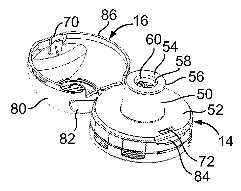
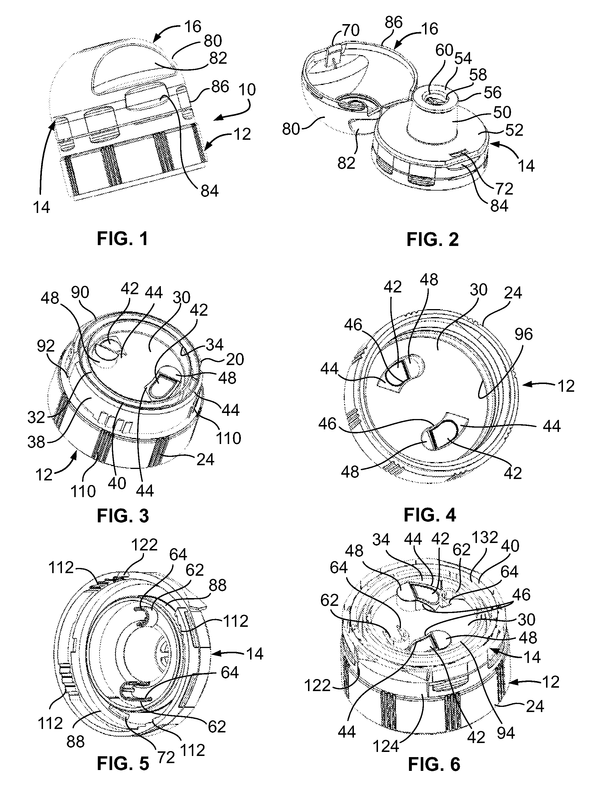
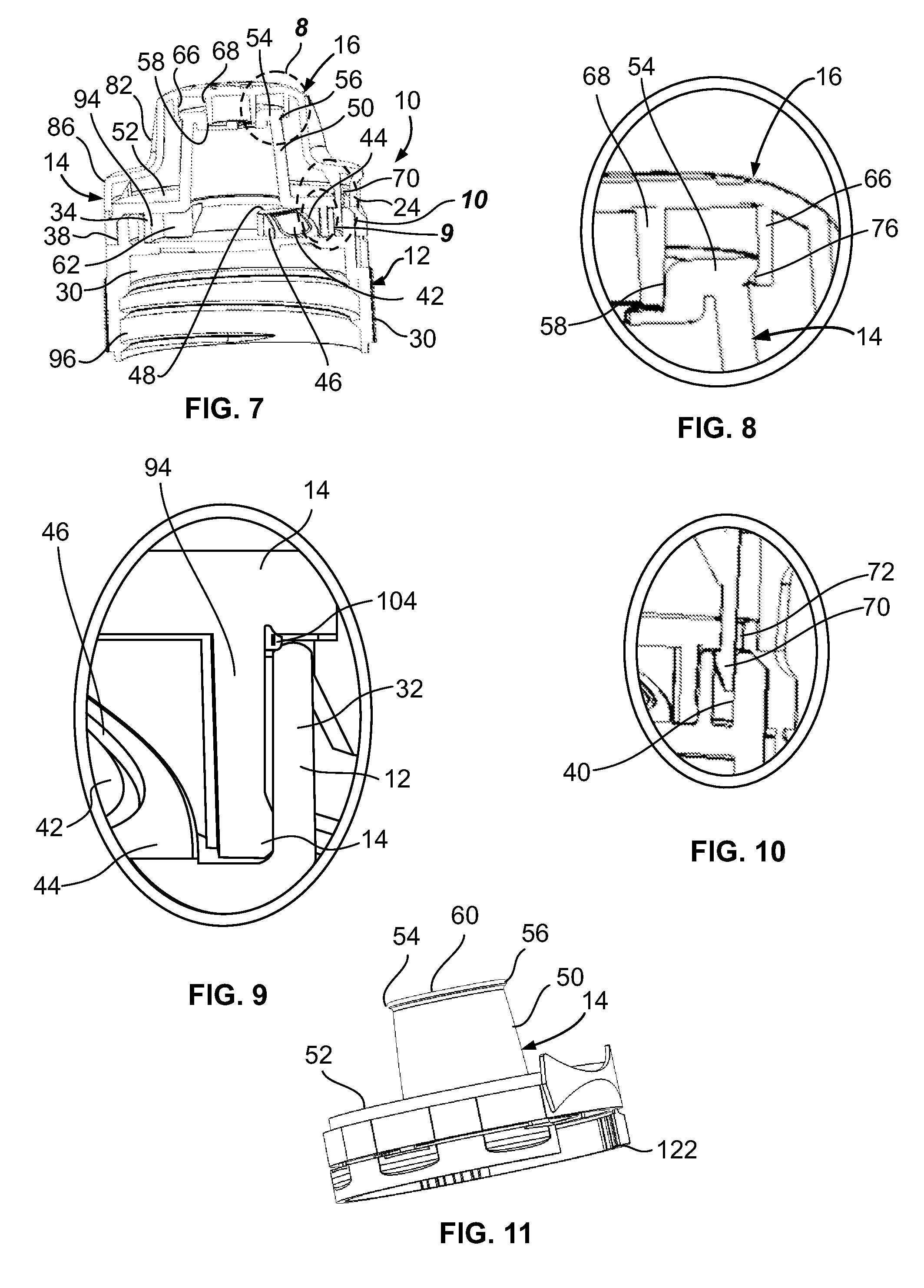
FIGS. 1-12 illustrate a dispensing closure 10 in accordance with an illustrated embodiment of the disclosure for a bottle or other vessel that contains fluids or liquids. The dispensing closure 10 comprises a base member 12 engageable with the bottle, a spout member 14, and a cap member 16 hingedly secured or otherwise attached to the spout member by a living hinge or the like. The dispensing closure 10 may be constructed of any suitable plastic or may be constructed of any other material in accordance with other embodiments of the present disclosure. The base member 12 is comprised of a body 20 and a lower skirt 24. The body 20 includes an enclosure surface 30, a rim 32 surrounding and extending vertically from the enclosure surface 30 that define an interior bore 34, and an external rim 38 that defines a slot 40. The enclosure surface 30 is circular and the body 20 seals the bottle and prevents fluid flow from the bottle into the bore 34. The base member 12 and spout member 14 hav...


PUM


Abstract

A dispensing closure for a vessel comprising a base member and a spout member engaged with the base member. The base member including a rupture member having a camming surface and the spout member having a cam actuator for engaging the camming surface to rupture the rupture member during twisting of the spout member in a first direction relative to the base member from a sealed position to a flow position to define a flow opening in the base member to permit fluid flow through the flow opening. The dispensing closure may include a pair of spaced rupture members and cam actuators. The dispensing closure may include a cap member hingedly attached to the spout member. The dispensing closure may include tamper evidency ring or other structure and a locking mechanism configured to lock the cap member in the closed position until the cap member and spout are rotated a sufficient distance to break the tamper evidency ring.

Description

BACKGROUNDThe present disclosure is directed to a reclosable dispensing closure for a bottle or other fluid vessel.Reclosable dispensing closures have been employed with a wide variety of products, including water, juices, condiments and detergents. The dispensing closure can be opened and closed without removing or separating any portion of the dispensing closure from the container.There are several styles of reclosable dispensing closures currently commercially available. For example, pull / push and screw type are two common designs. In both of these popular designs, the common theme is that there is a base and a spout installed together in an assembly. These designs rely upon multiple sealing surfaces to create an airtight dispensing closure for distribution and handling of the product.A disadvantage of these designs is that sealing is not consistent because of manufacturing tolerances, slight burrs, and other manufacturing and assembly irregularities. As a result, current reclosa...

Claims


Application Information

Patent Timeline
Patent Type & Authority Applications(United States)
IPC IPC(8): B67D1/00
CPCB65D47/0804B65D51/222B65D2251/0071B65D2251/0025B65D2101/0023B65D2401/15
Inventor SWANICK, KEN P.
Owner CALIBER CLOSURES
Why Eureka
Try Eureka