Vehicle wheel

a technology for vehicles and wheels, applied in the field of vehicles, can solve the problem of no failure safe for a case in which the sub-air chamber is provided by any possibility, and achieve the effect of efficient us

Active Publication Date: 2011-03-10
HONDA MOTOR CO LTD
View PDF6 Cites 33 Cited by
  • Summary
  • Abstract
  • Description
  • Claims
  • Application Information

AI Technical Summary

Benefits of technology

[0025]According to the vehicle wheel, the spacer is efficiently used as a portion which retains the communicating member protruding from the sub-air-chamber member, and the plural sub-air-chamber members each having the protruding communicating member are made successive across the whole circumference of the wheel via respective spacers. Also, according to the vehicle wheel, because each communicating member is surrounded by the spacer, it is possible to prevent the communicating member from being damaged at the time of tire removal and attachment work.
[0026]According to the present invention, there is provided a vehicle wheel that can suppress any detachment of a sub air chamber from a well portion when a fixing member between the sub air chamber and the well portion becomes defective by any possibility.

Problems solved by technology

According to the conventional vehicle wheel (see, for example, JP 2009-074595A), however, although the sub air chamber is surely fixed to the well portion because of the spring elasticity of the edge, no fail safe for a case in which the sub air chamber is detached by any possibility is provided.

Method used


Image

  • Vehicle wheel
  • Vehicle wheel
  • Vehicle wheel

Examples


Embodiment Construction

[0044]A detailed explanation will be given of embodiments of the present invention with reference to the accompanying drawings.

[0045]>

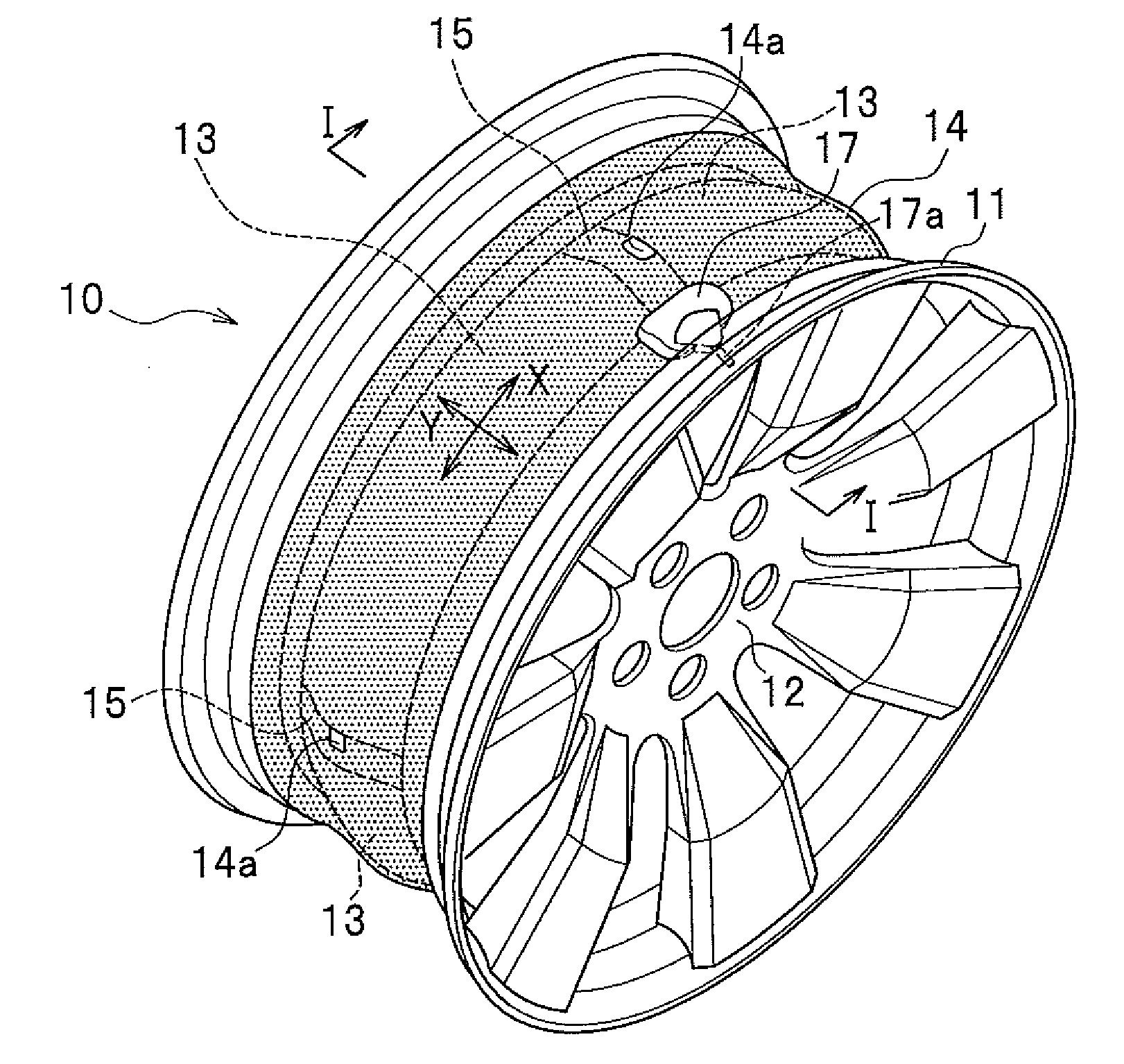
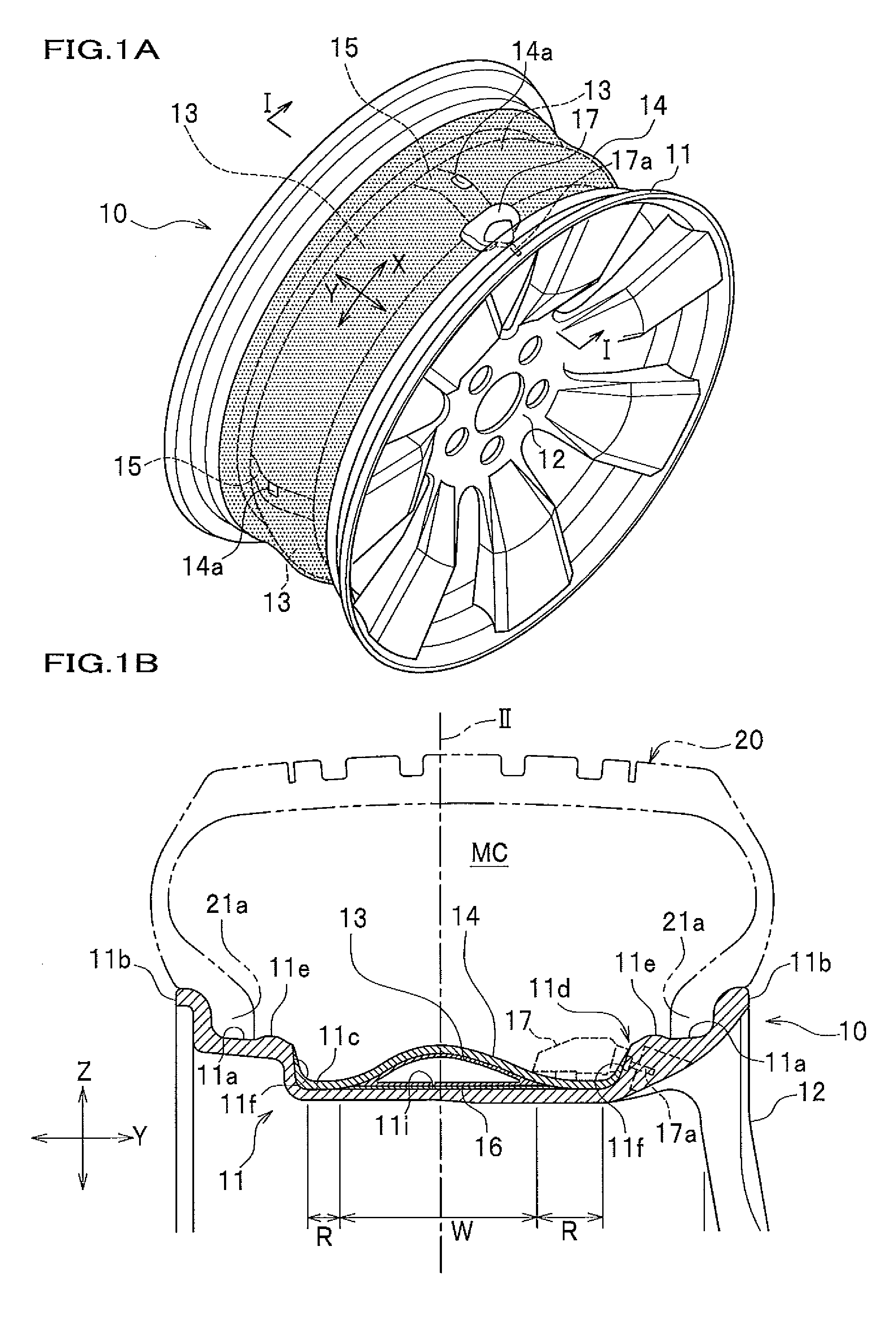
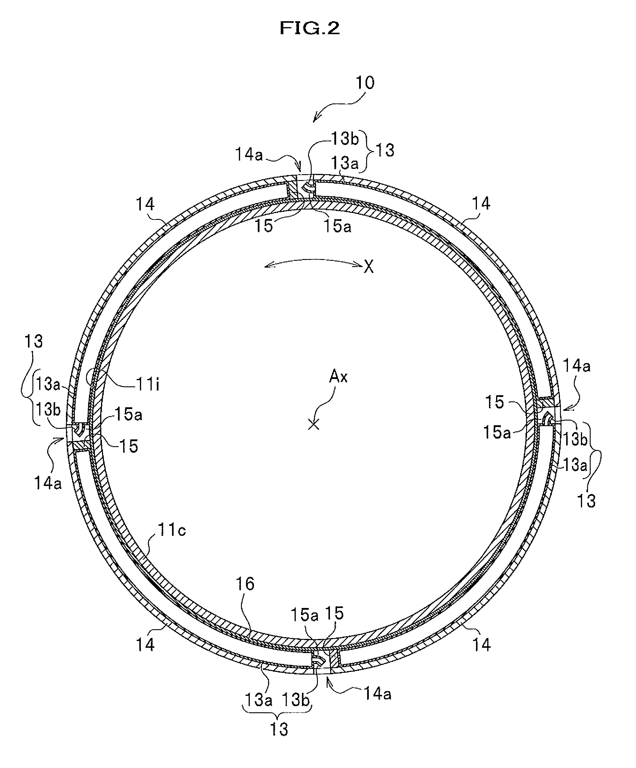
[0046]As shown in FIG. 1A, a vehicle wheel 10 of this embodiment includes a rim 11, and a disc 12 for supporting the rim 11 and being mounted on a hub (not shown).

[0047]As shown in FIG. 1B, the rim 11 includes bead seating portions 11a, 11a formed at both ends of the rim 11 in a width direction Y (hereinafter, a rim width direction Y), rim flange portions 11b, 11b bent in an L shape from respective bead seating portions 11a, 11a, and a well portion 11c which is a portion between the bead seating portions 11a, 11a concaved inwardly of (lower side of FIG. 1B) a wheel diameter direction Z. Hump portions 11e, 11e upraising outwardly of the wheel diameter direction Z are formed at respective inner side ends of the bead seating portions 11a, 11a.

[0048]A bead part 21a of a tire 20 is attached to the bead seating portion 11a. Accordingly, a tire air chamber ...


PUM


Abstract

There is provided a vehicle wheel that can suppress any detachment of a sub air chamber from a well portion when a fixing member between the sub air chamber and the well portion becomes defective by any possibility. A vehicle wheel comprises a sub-air-chamber member which reduces any air column resonance of a tire and which is disposed on an outer circumference surface of a well portion of a rim. The sub-air-chamber member is fixed on the well-portion outer circumference surface, the sub-air-chamber member is covered by a cover made of a rubber from an external side, and the cover is fixed on an outer circumference surface of the rim at both sides of the sub-air-chamber member in a rim width direction.

Description

CROSS REFERENCE TO RELATED APPLICATIONS[0001]This application claims the foreign priority benefit under Title 35, United States Code, §119(a)-(d) of Japanese Patent Application No. 2009-206698, filed on Sep. 8, 2009 in the Japan Patent Office, the disclosure of which is herein incorporated by reference in its entirety.BACKGROUND OF THE INVENTION[0002]1. Field of the Invention[0003]The present invention relates to a vehicle wheel including a sub air chamber that reduces an air column resonance of a tire.[0004]2. Description of the Related Art[0005]In general, it is known that an air column resonance (cavity resonance) generated in a tire air chamber is a factor of a vehicular road noise. Such air column resonance is a phenomenon in which an air column in the air chamber resonates in response to vibrations transmitted from a road surface to a tread portion of a tire while a vehicle is traveling.[0006]Conventionally, there is known a vehicle wheel having a sub air chamber which reduces...

Claims


Application Information

Patent Timeline
Patent Type & Authority Applications(United States)
IPC IPC(8): B60B21/12
CPCB60B1/06B60B21/12B60B21/023
Inventor NAGATA, SHINYAKITAGAWA, MASASHI
Owner HONDA MOTOR CO LTD
Why Eureka
Try Eureka