Harnessing power through electromagnetic induction utilizing printed coils

Active Publication Date: 2011-03-10
APPLE INC
View PDF58 Cites 42 Cited by
  • Summary
  • Abstract
  • Description
  • Claims
  • Application Information

AI Technical Summary

Benefits of technology

[0003]Systems for harnessing power through electromagnetic induction utilizing printed coils are provided. A system can include one or more moveable magnets adjacent to printed coils on a circuit. For example, a system can include one or more magnets that are operative to move alongside a circuit board that includes printed coils. The one or more magnets may move, for example, when a user shakes the system or when the user walks or runs while holding the device. The movement of the one or more magnets may create an electromotive force (e.g., a voltage) across the printed coils, and this force may be used to generate electric power.
[0004]Printed coils can be formed using any suitable technique for printing circuit boards. For example, printed coils can be formed by depositing copper on a substrate to form traces in the shape of coils or selectively etching copper from a subst

Problems solved by technology

Moreover, the wire coils and magnet of a traditional system are often hous

Method used


Image

  • Harnessing power through electromagnetic induction utilizing printed coils
  • Harnessing power through electromagnetic induction utilizing printed coils
  • Harnessing power through electromagnetic induction utilizing printed coils

Examples


Embodiment Construction

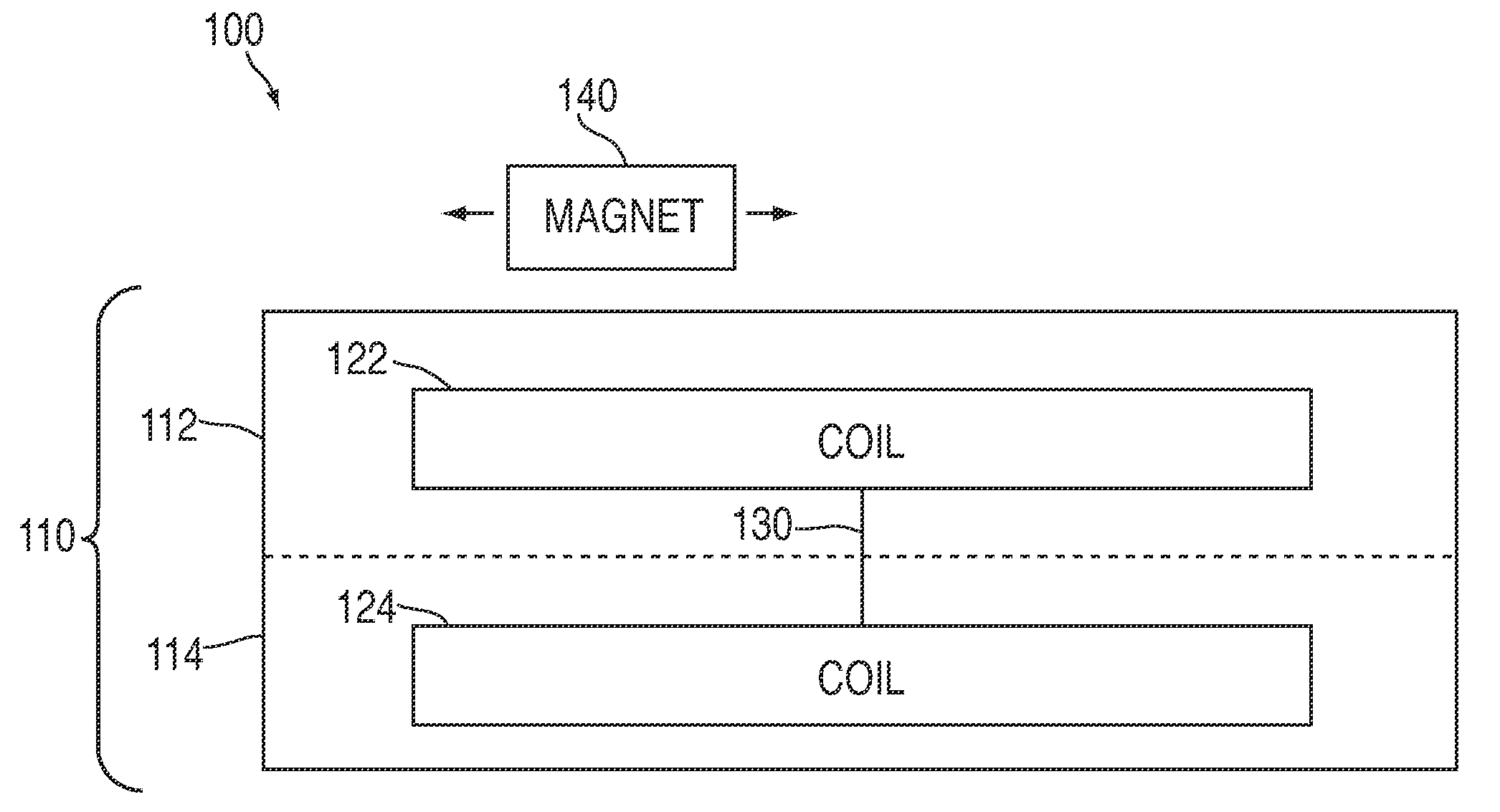
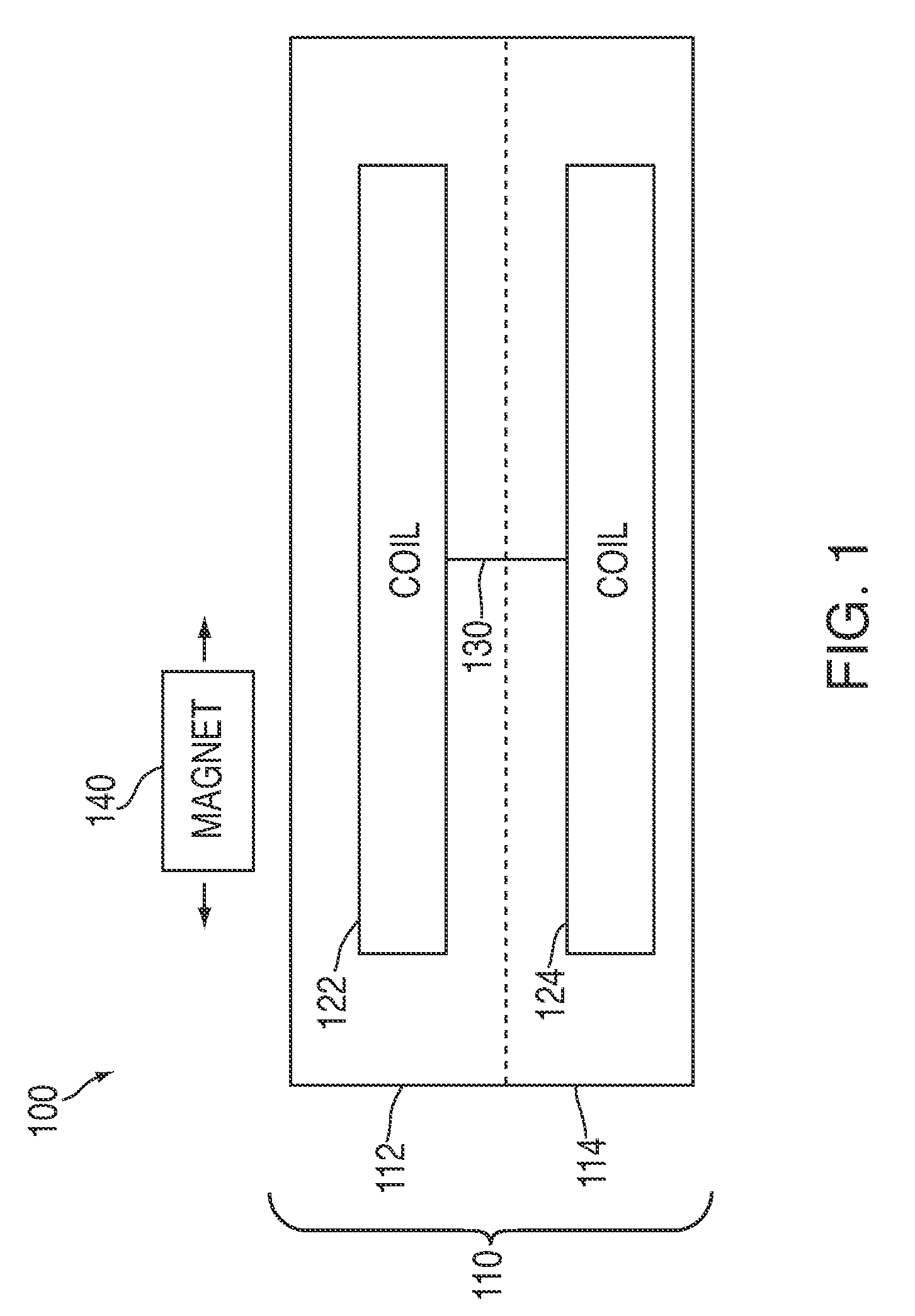
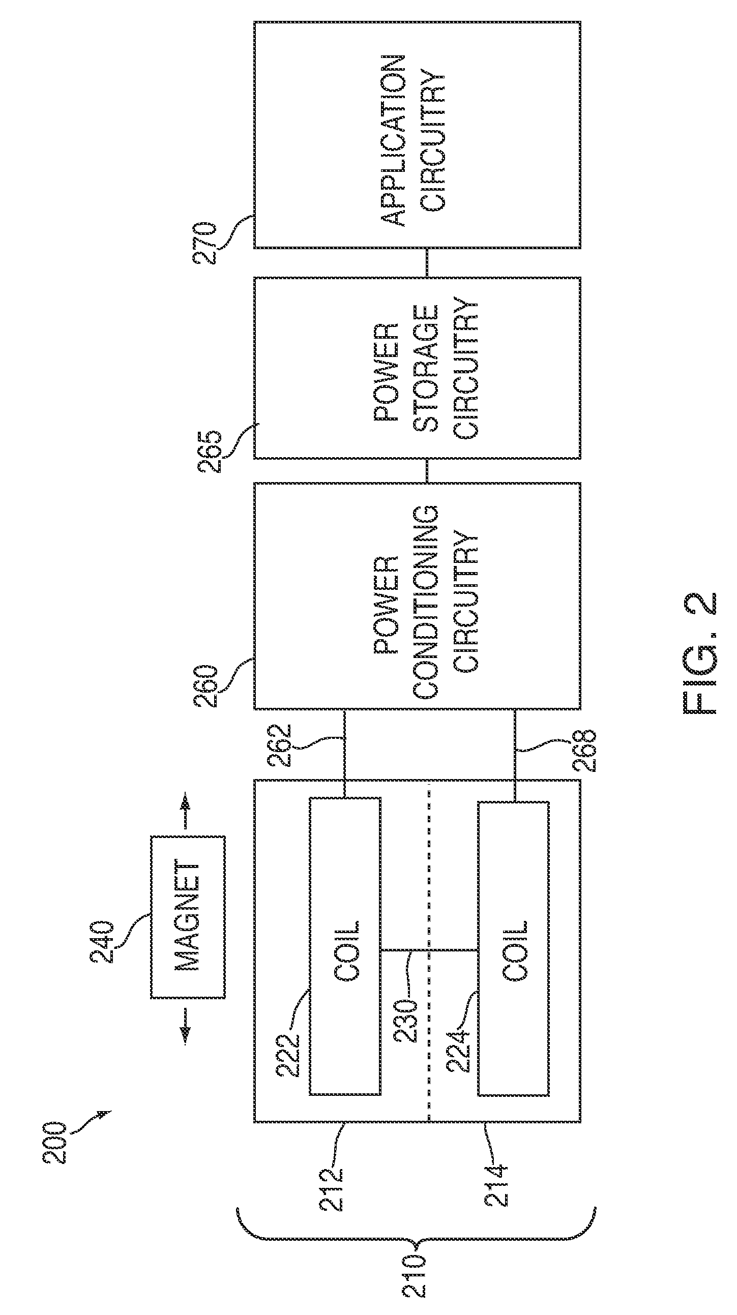
[0027]Electromagnetic induction can cause an electromotive force across an array of printed coils on a circuit board when the array moves through a magnetic field. For example, a voltage potential may be measured when an array of printed coils moves relative to a magnet. The magnitude of the electromotive force, and the associated electrical power, may be the result of various factors. For example, the magnitude of the electromotive force may be based on the length of the conductor moving through the magnetic field (e.g., the number of turns in a printed coil). In some embodiments, coils can be printed on a circuit board in dense configurations that offer a greater concentration of coil turns. Moreover, coils printed on a circuit board may be more efficiently integrated with other components of a system and, therefore, allow for a generally smaller system.

[0028]FIG. 1 includes electromagnetic induction system 100 in accordance with one embodiment of the invention. System 100 can inc...


PUM


Abstract

Systems for harnessing power through electromagnetic induction utilizing printed coils are provided. A system can include one or more moveable magnets adjacent to printed coils on a circuit. For example, a system can include one or more magnets that are operative to move alongside a circuit board that includes printed coils. The one or more magnets may move, for example, when a user shakes the system or when the user walks or runs while holding the device. The movement of the one or more magnets may create an electromotive force (e.g., a voltage) across the printed coils, and this force may be used to generate electric power.

Description

BACKGROUND OF THE INVENTION[0001]This is directed to systems for harnessing power through electromagnetic induction.[0002]Traditional systems for harnessing power through electromagnetic induction involve wire coils, a magnet, and relative movement between the two. To achieve meaningful output power, a traditional system typically includes thick coils of wire that add to the system's overall size. Moreover, the wire coils and magnet of a traditional system are often housed in an inefficient manner that further adds to the system's overall size.SUMMARY OF THE INVENTION[0003]Systems for harnessing power through electromagnetic induction utilizing printed coils are provided. A system can include one or more moveable magnets adjacent to printed coils on a circuit. For example, a system can include one or more magnets that are operative to move alongside a circuit board that includes printed coils. The one or more magnets may move, for example, when a user shakes the system or when the u...

Claims


Application Information

Patent Timeline
IPC IPC(8): H02K35/00H01F41/00
CPCH02K3/26H02K3/47Y10T29/4913Y10T29/49826Y10T29/4902H02K35/02
Inventor LIN, GLORIARAHUL, PAREETROSENBLATT, MICHAELNAKAJIMA, TAIDOGERMANSDERFER, BRUNODASGUPTA, SAUMITRO
Owner APPLE INC
Why Eureka
Try Eureka