Apparatus and method for identifying a faulted phase in a shunt capacitor bank

a technology of faulted phase and shunt capacitor, which is applied in the direction of instruments, emergency protective arrangements for limiting excess voltage/current, and base element modifications. it can solve the problems of affecting the operation of the base element. it is more difficult to determine the faulted phase of the ungrounded shunt capacitor bank

Active Publication Date: 2011-03-10
SCHWEITZER ENGINEERING LABORATORIES
View PDF23 Cites 24 Cited by
  • Summary
  • Abstract
  • Description
  • Claims
  • Application Information

AI Technical Summary

Benefits of technology

[0014]According to an aspect of the invention, disclosed is an apparatus and method for identifying a faulted phase in at least one shunt capacitor bank. The apparatus may be used to monitor and protect capacitor arrangements which are fused or not fused. The apparatus may further be used for single WYE type, double WYE type, H bridge type, or other comparable arrangements. The apparatus generally includes a sampling circuit for sampling current or vol

Problems solved by technology

Multiple failures in a plurality of capacitors in the capacitor unit cause the fuse to blow, interrupting the fault current.
If one of the capacitor elements fails, the fus

Method used


Image

  • Apparatus and method for identifying a faulted phase in a shunt capacitor bank
  • Apparatus and method for identifying a faulted phase in a shunt capacitor bank
  • Apparatus and method for identifying a faulted phase in a shunt capacitor bank

Examples


example 1

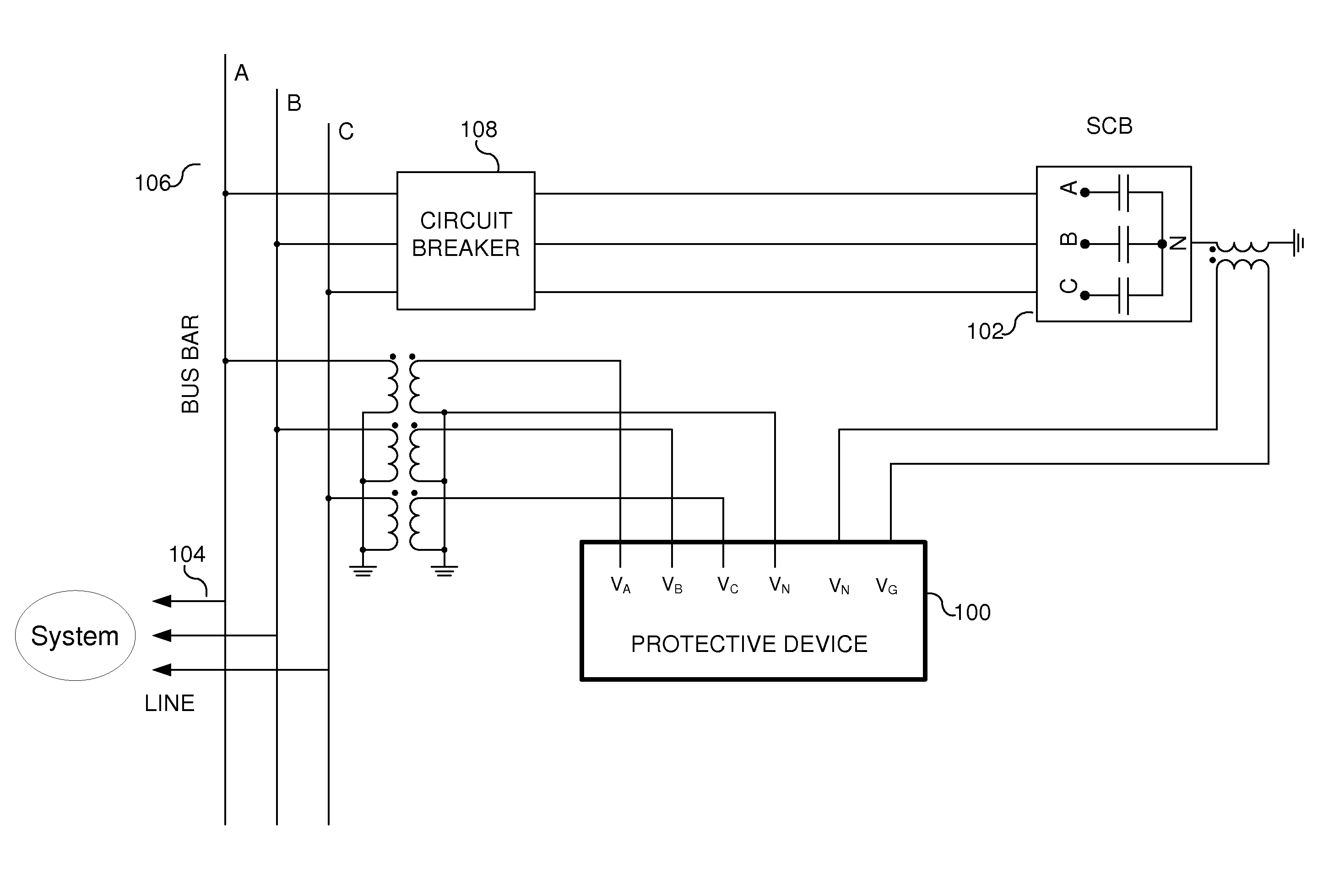
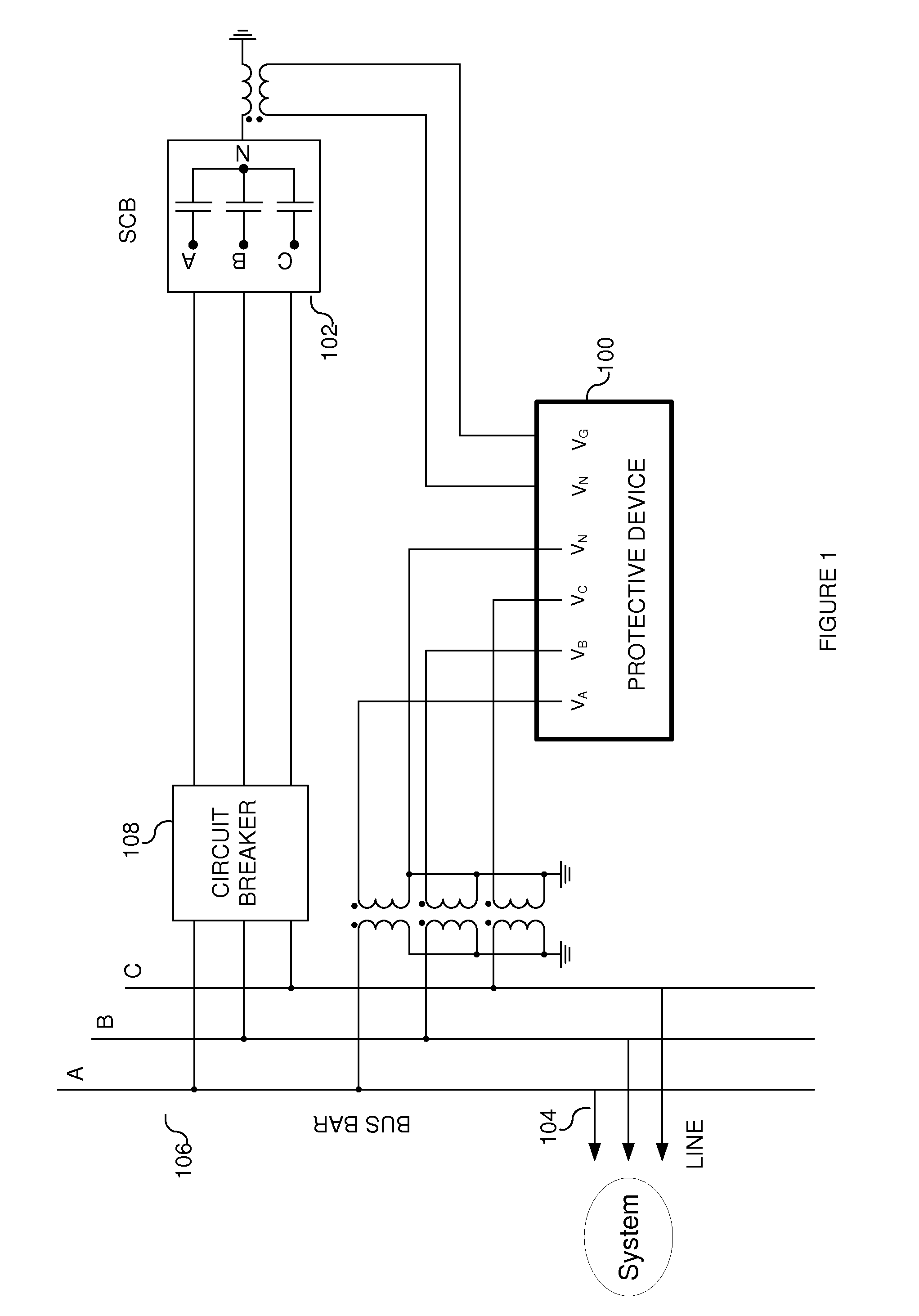
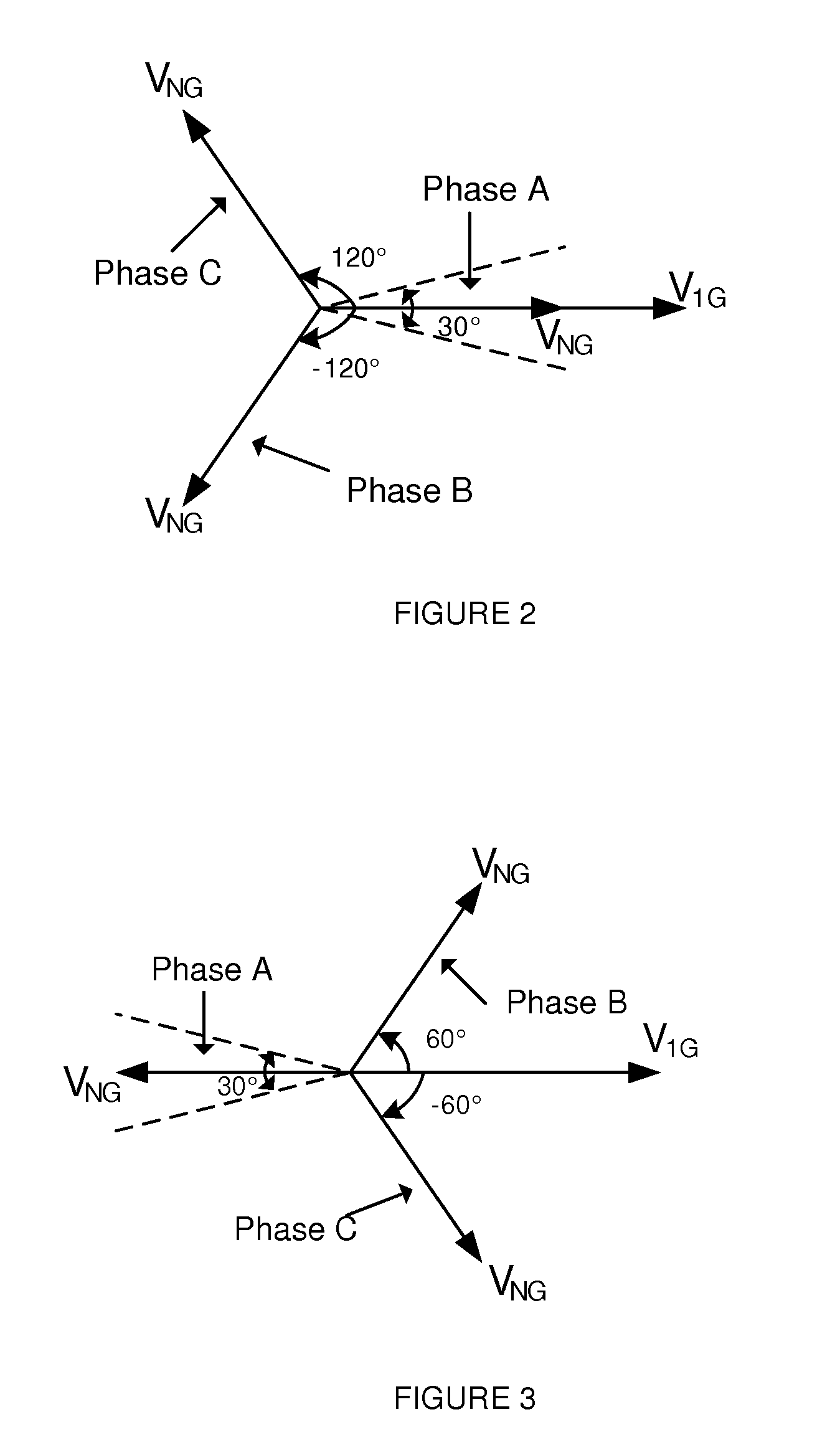
[0064]FIGS. 12-14 illustrate examples of the protective device logic that was used to identify the faulted phase of an ungrounded shunt capacitor bank in a single WYE arrangement that was not fused. The shunt capacitor bank included 5 strings per phase, wherein each string had 12 units in series and each unit had 6 elements (or capacitors) in series. As shown in the Figures, the phase angle of the compensated neutral voltage (∠NG) was compared with the positive-sequence voltage phase angle (∠1G) at the busbar. In this arrangement, the source voltage was 230 kV and a neutral potential transformer measured the unbalance in the shunt capacitor bank. As shown in FIG. 12, there was a fault in capacitors associated with Phase A. More specifically, there was a compensated neutral voltage magnitude of 38.3V and a compensated neutral voltage phase of about −0.5°. As shown in FIG. 13, there was a fault in the capacitors associated with Phase-B. More specifically, there was a compensated neutr...

example 2

[0065]FIGS. 15-20 illustrate examples of the protective device logic that was used to identify the faulted phase of two ungrounded shunt capacitor banks in a double WYE arrangement that was not fused. The shunt capacitor bank included 5 strings per phase on the left bank and 4 strings per phase on the right bank, wherein each string had 12 units in series and each unit had 6 elements. As shown in the Figures, the phase angle of the compensated neutral current (∠NG) was compared with the positive-sequence current phase angle (∠1G).

[0066]As shown in FIG. 15, there was a fault associated with the capacitors of Phase-A in the left shunt capacitor bank. More specifically, there was a compensated neutral current magnitude of 130.1 mA and a compensated neutral current phase of about −0.4°. As shown in FIG. 16, there was a fault associated with the capacitors of Phase-A in the right capacitor bank. More specifically, there was a compensated neutral current magnitude of 162.7 mA and a compen...


PUM


Abstract

An apparatus and method is provided for identifying a faulted phase in at least one shunt capacitor bank. The apparatus generally includes a sampling circuit for sampling current or voltage signals associated with the shunt capacitor bank. A microcontroller is coupled to the sampling circuit and programmed to measure a compensated neutral point phase angle from the sampled signal, and compare the compensated neutral point phase angle with a fixed reference phase angle to identify the faulted phase of the shunt capacitor bank. The method generally includes the steps of sampling a current or voltage signal associated with the shunt capacitor bank, determining a compensated neutral point phase angle from the sampled signal, and comparing the compensated neutral point phase angle with a fixed reference phase angle to identify the faulted phase of the shunt capacitor bank. The invention also relates to an apparatus and method for identifying the location of the fault (e.g., the section of the bank) in a double ungrounded shunt capacitor bank or double WYE shunt capacitor bank.

Description

RELATED APPLICATION[0001]None.BACKGROUND OF THE INVENTION[0002]The present invention generally relates to power system protection, and more specifically, to an apparatus and method for identifying a faulted phase in ashunt capacitor bank. The invention also relates to an apparatus and method for identifying the location of the fault (e.g., the section of the bank) in a double ungrounded shunt capacitor bank or double WYE shunt capacitor bank.[0003]Electric utility systems or power systems are designed to generate, transmit and distribute electrical energy to loads. In order to accomplish this, power systems generally include a variety of power system elements such as electrical generators, electrical motors, power transformers, power transmission lines, buses and capacitors, to name a few. As a result, power systems must also include protective devices and procedures to protect the power system elements from abnormal conditions such as electrical short circuits, overloads, frequency...

Claims


Application Information

Patent Timeline
IPC IPC(8): G01R31/08
CPCH02H7/16H02H3/042
Inventor SAMINENI, SATISHLABUSCHAGNE, CASPER A.
Owner SCHWEITZER ENGINEERING LABORATORIES
Why Eureka
Try Eureka