Touch panel

a technology of touch panel and touch control circuit, which is applied in the field of touch panel, can solve the problems of low yield rate of integrated/in-cell type touch panel and additive-type touch panel, and affect the ability of electrostatic discharge protection, etc., and achieve the effect of favorable ability of esd protection

Active Publication Date: 2011-03-10
AU OPTRONICS CORP
View PDF23 Cites 114 Cited by
  • Summary
  • Abstract
  • Description
  • Claims
  • Application Information

AI Technical Summary

Benefits of technology

[0008]The disclosure provides a touch panel having a fav...

Problems solved by technology

As a consequence, the additive-type touch panel inevitably has a certain thickness.
However, in terms of fabrication, the integrated/in-cell type touch panel and the additive-type touch panel both encounter the problem of low yield rate resulting from electrostatic discharge.
Such a problem is especially crucial to the integrated/in-cell type ...

Method used


Image

  • Touch panel
  • Touch panel
  • Touch panel

Examples


first embodiment

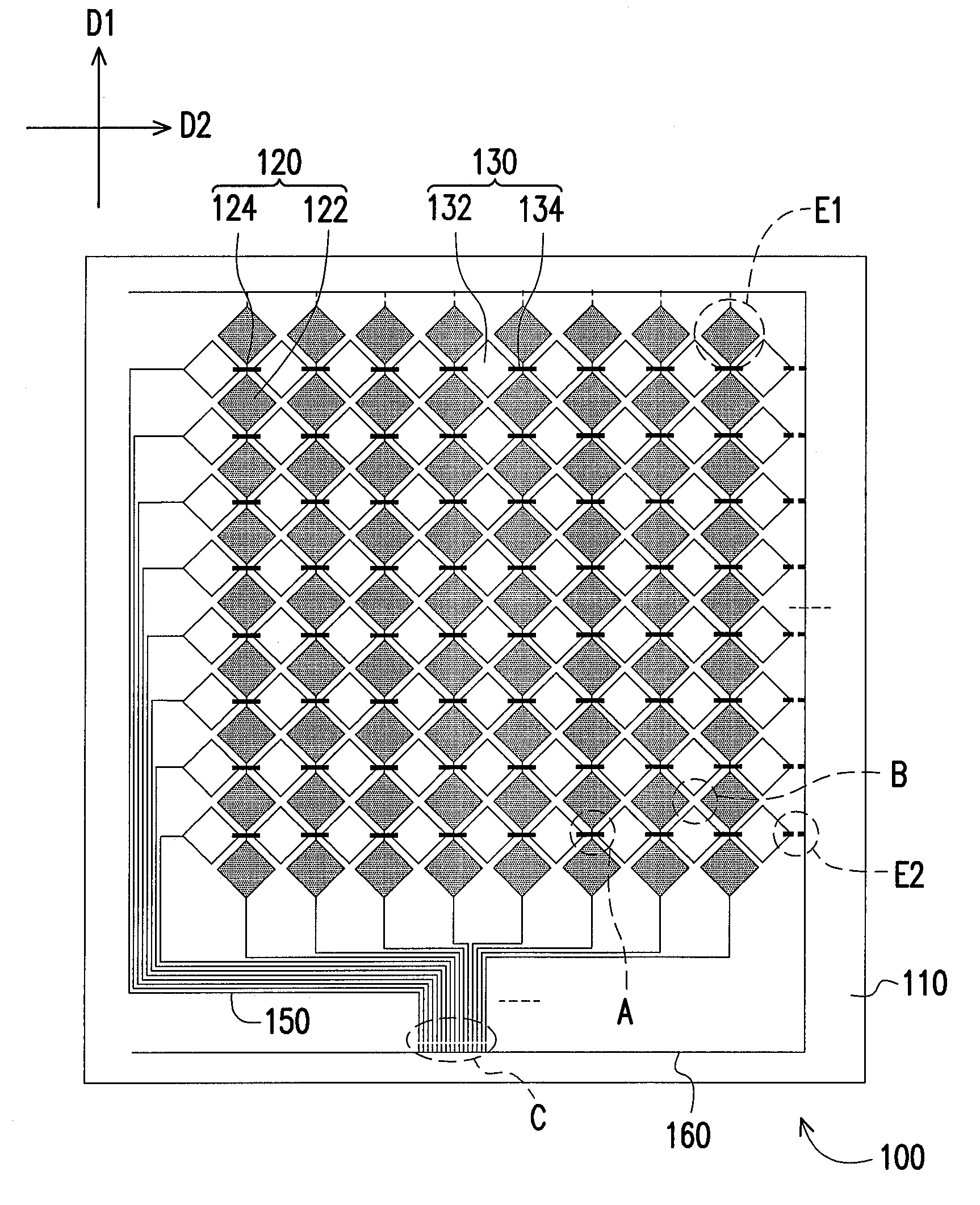
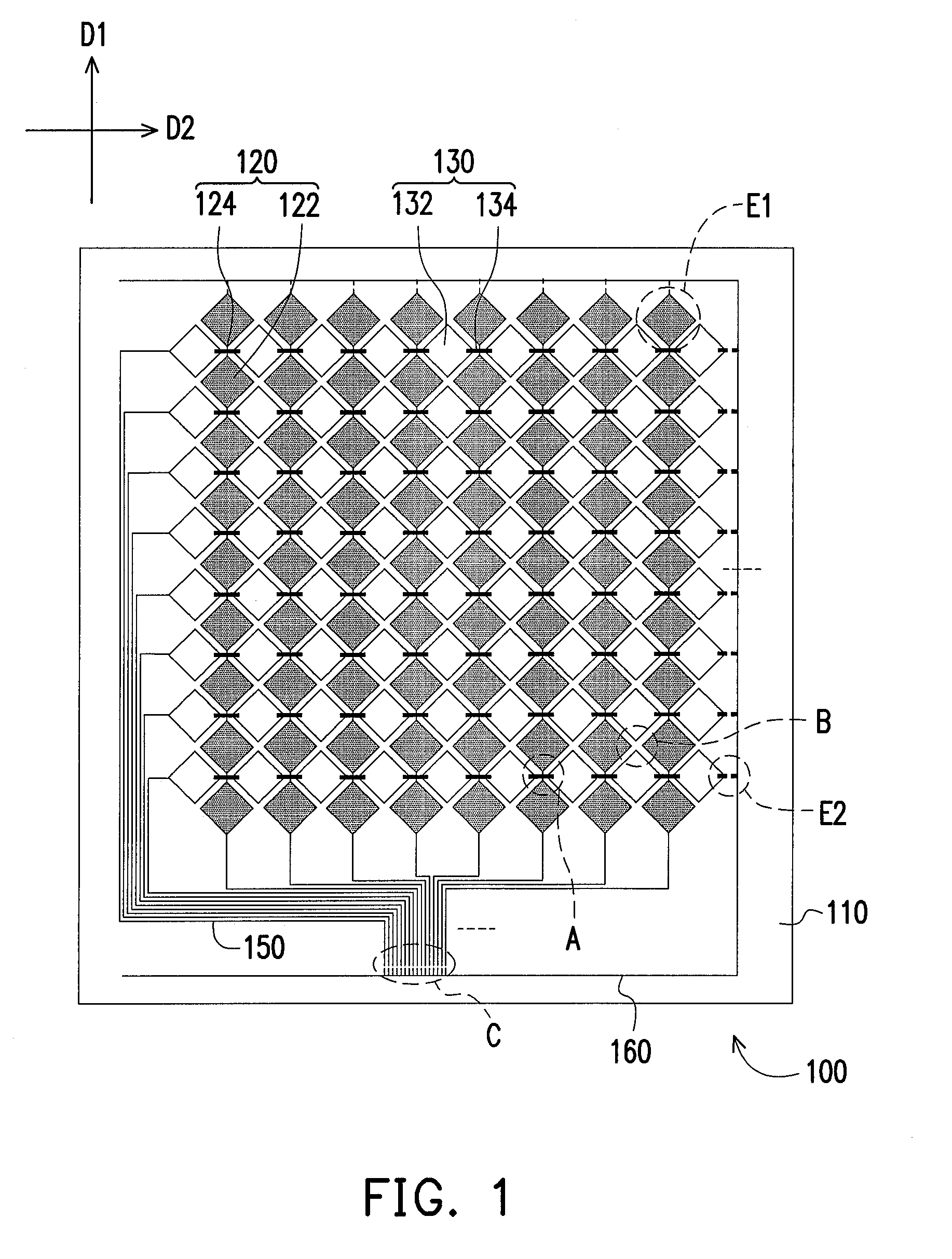
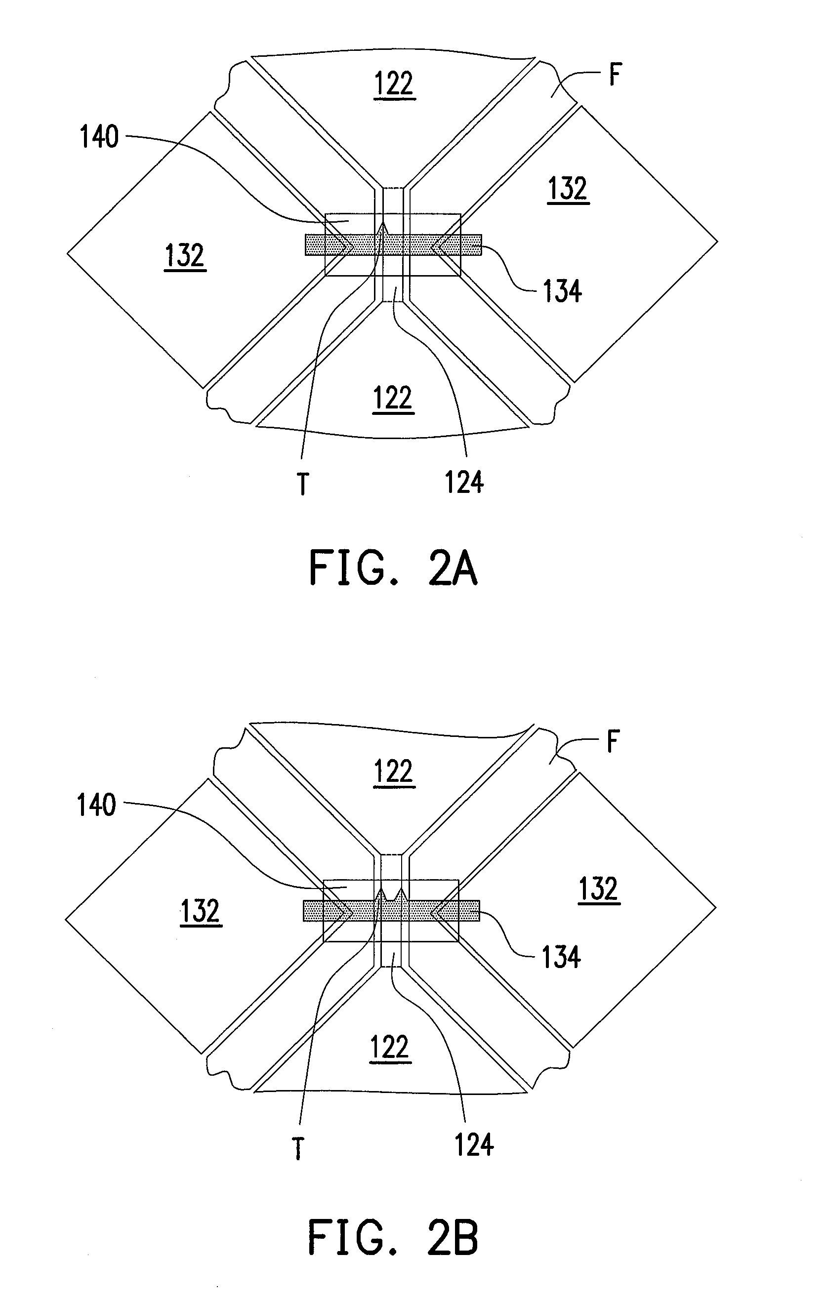
[0025]FIG. 1 is a schematic view of a touch panel according to the first embodiment of the disclosure, and FIGS. 2A˜2C are enlarged views of an area A in FIG. 1. Referring to FIGS. 1 and 2A, a touch panel 100 described in this embodiment includes a substrate 110, a plurality of first sensing series 120, and a plurality of second sensing series 130. The first sensing series 120 are disposed on the substrate 110. Moreover, the first sensing series 120 extend along a first direction D1 and are electrically insulated from one another. In this embodiment, each of the first sensing series 120 includes a plurality of first sensing pads 122 and a plurality of the first bridge portions 124, wherein each of the first bridge portions 124 is electrically connected between two neighboring first sensing pads 122. The second sensing series 130 are also disposed on the substrate 110. In addition, the second sensing series 130 extend along a second direction D2 and are electrically insulated from on...

second embodiment

[0043]FIG. 6 is a schematic view of a touch panel according to the second embodiment of the disclosure. Referring to FIG. 6, in a touch panel 200 of this embodiment, second sensing series 230 which are arranged in a row can be divided into two second sensing series 230, wherein the second sensing series 230 on the left are electrically connected with a sensing signal transmission line 250 disposed on the left side, and the second sensing series 230 on the right are electrically connected with a sensing signal transmission line 250 disposed on the right side. To be more specific, the second sensing series 230 are divided into two groups which are respectively electrically connected with two groups of sensing signal transmission lines 250.

[0044]FIGS. 7A˜7C are enlarged views of an area D in FIG. 6. Referring to FIGS. 6 and 7A, the touch panel 200 described in this embodiment includes a substrate 210, a plurality of first sensing series 220, and a plurality of the second sensing series...


PUM


Abstract

A touch panel including a substrate, a plurality of first sensing series, and a plurality of second sensing series is provided. The first sensing series and the second sensing series are disposed on the substrate. The first sensing series extend along a first direction and are electrically insulated from each other. Each of the first sensing series includes a plurality of first sensing pads and a plurality of first bridge portions connected between the first sensing pads. The second sensing series extend along a second direction and are electrically insulated from each other. Each of the second sensing series includes a plurality of second sensing pads and a plurality of second bridge portions connected between the second sensing pads. Each of the first bridge portions and one of the second bridge portions are intersected, and at least one of the second bridge portions has at least one electrostatic discharge tip.

Description

CROSS-REFERENCE TO RELATED APPLICATION[0001]This application claims the priority benefit of Taiwan application serial no. 98130065, filed on Sep. 7, 2009. The entirety of the above-mentioned patent application is hereby incorporated by reference herein and made a part of specification.BACKGROUND OF THE DISCLOSURE[0002]1. Technical Field[0003]The disclosure relates to a touch panel, and in particular relates to a touch panel having a favorable capability of electrostatic discharge (ESD) protection.[0004]2. Description of Related Art[0005]Based on different sensing methods, touch panels can be categorized into the following types: resistive touch panel, capacitive touch panel, optical touch panel, acoustic-wave touch panel, and electromagnetic touch panel. A capacitive touch panel is characterized by short response speed, good reliability, satisfactory durability, and so forth. Therefore, capacitive touch panels have been extensively applied in various kinds of electronic products. In...

Claims


Application Information

Patent Timeline
IPC IPC(8): G06F3/041
CPCG06F2203/04111G06F3/044G06F3/0446G06F3/0443
Inventor LIN, YU-CHUANLIU, SHENG-FAKUO, JING-TINLEE, HSIN-HUNGCHANG, WEI-JENCHEN, PEI-YUCHIU, YU-MEIMA, MEI-SHENGCHENG, KUO-HSING
Owner AU OPTRONICS CORP
Why Eureka
Try Eureka