Surface illumination apparatus and liquid crystal display using same

Inactive Publication Date: 2011-03-10
PANASONIC CORP
View PDF4 Cites 19 Cited by
  • Summary
  • Abstract
  • Description
  • Claims
  • Application Information

AI Technical Summary

Benefits of technology

[0011]This surface illumination apparatus can selectively illuminate

Problems solved by technology

In the above mentioned prior art, however, light utilization efficiency is high but the configuration of the optical system is complicated, t

Method used


Image

  • Surface illumination apparatus and liquid crystal display using same
  • Surface illumination apparatus and liquid crystal display using same
  • Surface illumination apparatus and liquid crystal display using same

Examples


embodiment 1

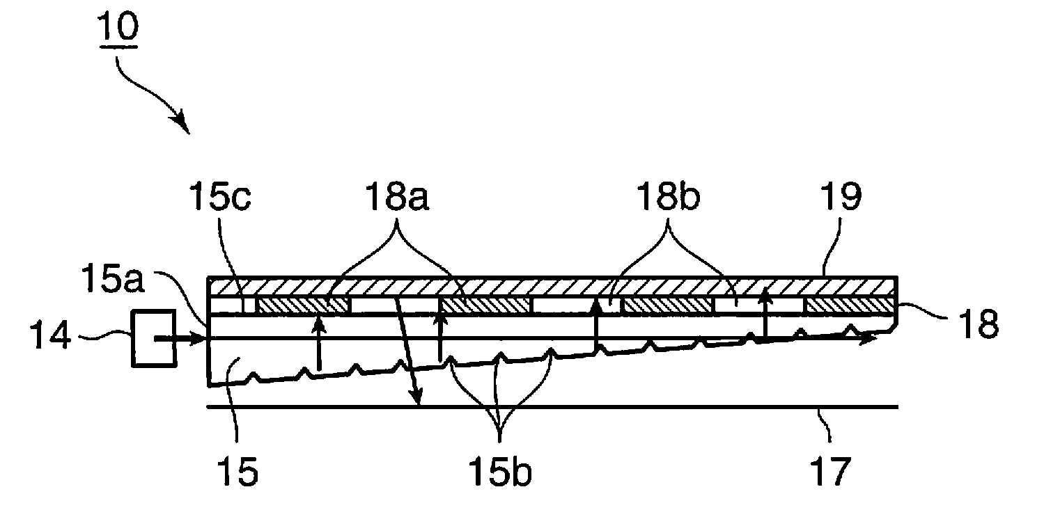
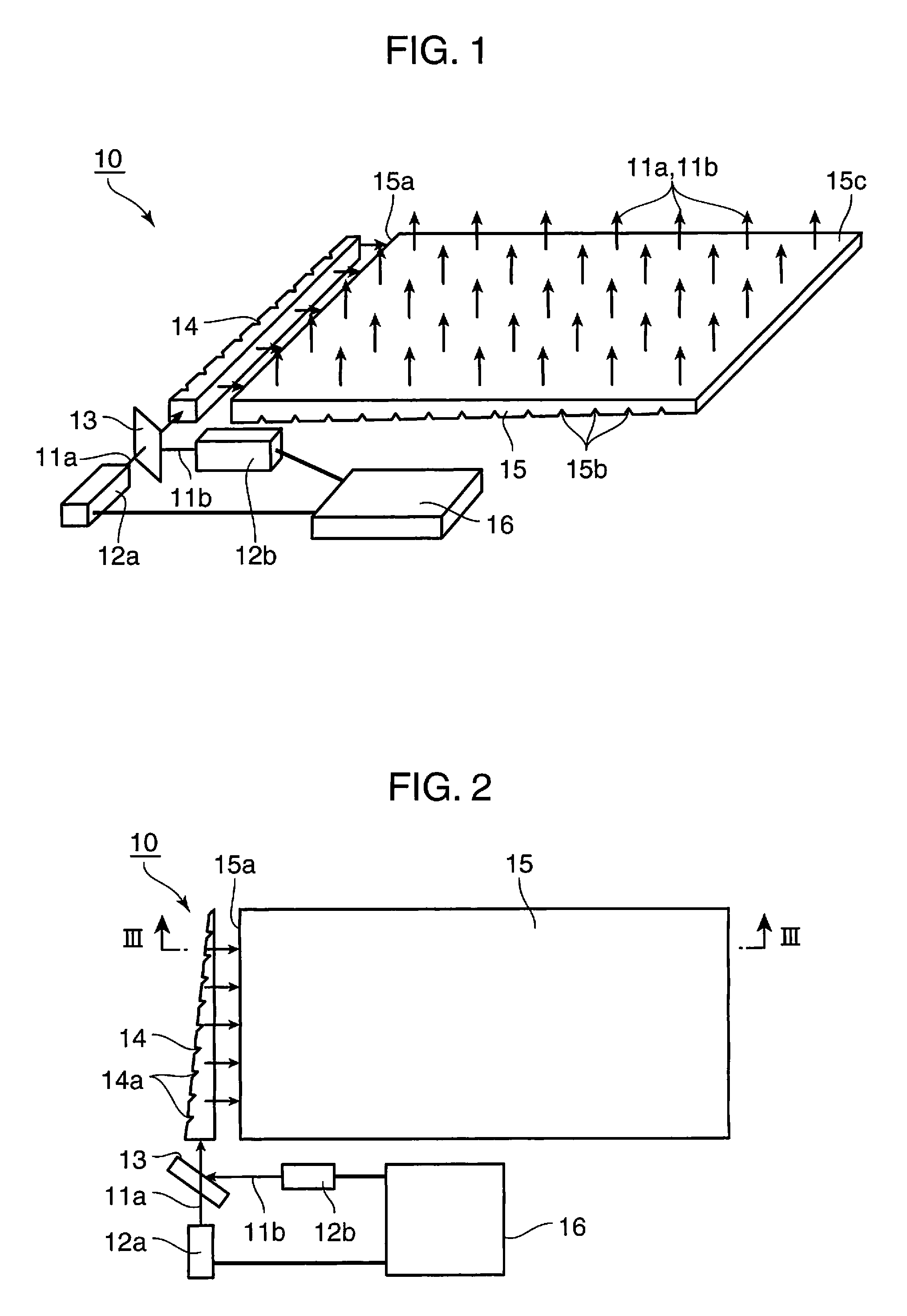
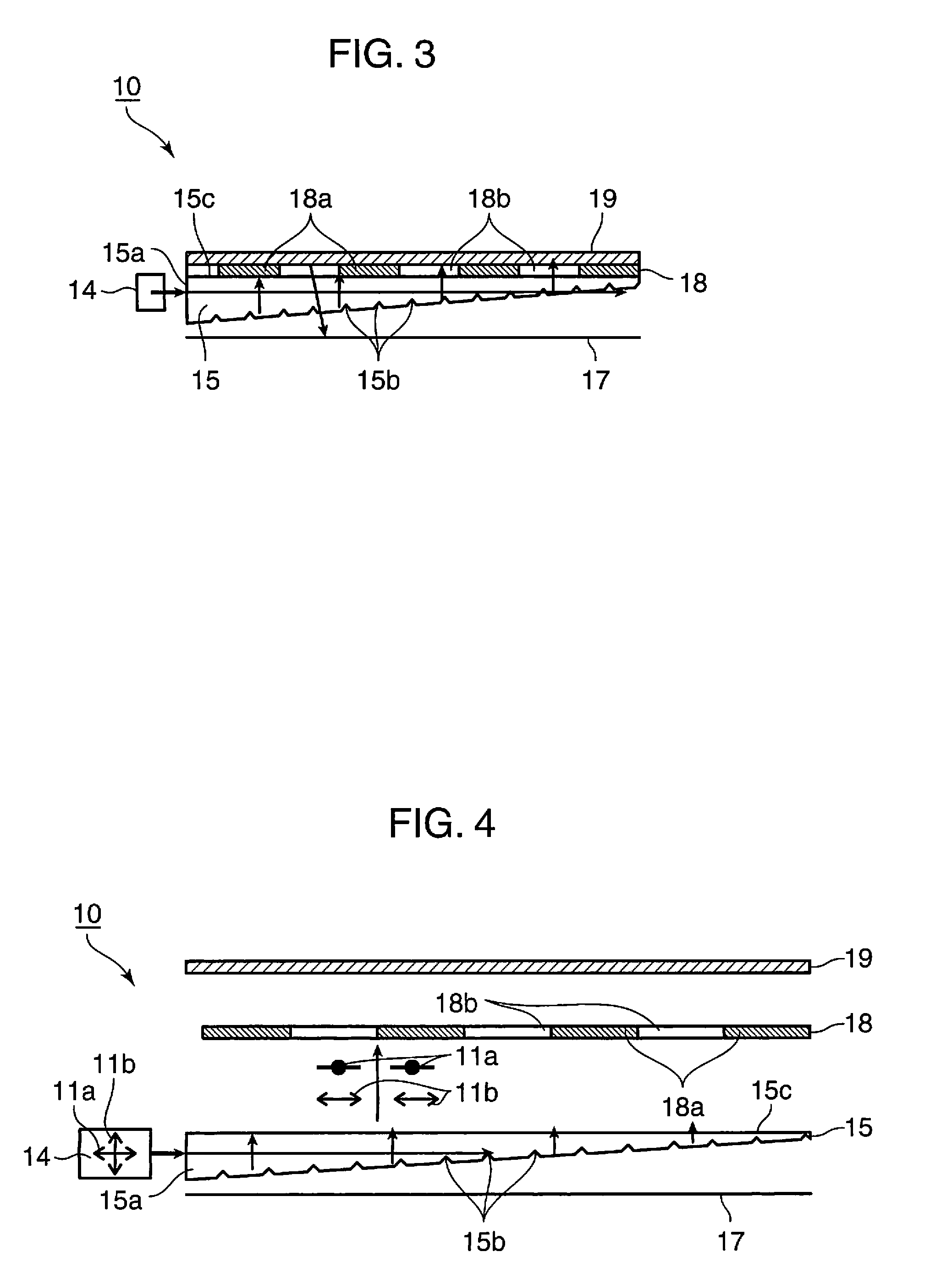
[0040]FIG. 1 to FIG. 3 are diagrams depicting a surface illumination apparatus 10 according to Embodiment 1 of the present invention, where FIG. 1 and FIG. 2 are a perspective view and a top view of a portion of the surface illumination apparatus 10 from which a polarizing filter 19, a polarizing modulation plate 18 and a reflection sheet 17 are removed, and FIG. 3 is a cross-sectional view of the surface illumination apparatus 10 sectioned at the III-III line in FIG. 2, including the polarizing modulation plate 18, the polarizing filter 19 and the reflection sheet 17.

[0041]This surface illumination apparatus 10 has light sources 12a and 12b which emit lights 11a and 11b respectively, a control unit 16 connected to the light sources 12a and 12b, a combiner 13 which combines the lights 11a and 11b, a light guiding bar 14 which linearly transforms the lights 11a and 11b, a light guiding plate 15 which transforms the linear lights into surface lights and emits the surface lights, the r...

embodiment 2

[0069]FIG. 12 to FIG. 14 are diagrams depicting a surface illumination apparatus 50 according to Embodiment 2 of the present invention, where FIG. 12 is a top view of the surface illumination apparatus 50 excluding the polarizing filter 19, polarizing modulation plate 58, ¼ wavelength plate 59, and a reflection sheet 17, and FIG. 13 and FIG. 14 are cross-sectional views of the surface illumination apparatus 50 sectioned at the XIII-XIII line in FIG. 12.

[0070]A major difference of the present surface illumination apparatus 50 from the surface illumination apparatus 10 of Embodiment 1 is that the linearly polarized lights 51a and 51b emitted from the light sources 52a and 52b are multiplexed by a combiner 13, then a 1 / 4 wavelength plate 53 is inserted, so as to transform the polarization of the lights 51a and 51b into rotatory polarized lights which turn in different directions from each other. As composing elements, the above mentioned ¼ wavelength plate 53 an ¼ wavelength plate 59 ...

embodiment 3

[0088]A liquid crystal display according to Embodiment 3 of the present invention will now be described with reference to FIG. 19 to FIG. 21. FIG. 19 shows the liquid crystal display 80 according to Embodiment 3 of the present invention, and FIG. 20 shows a top view of a surface illumination apparatus 90a which illuminates the liquid crystal panel 81 of the liquid crystal display 80 from the rear face. In FIG. 20, the polarizing modulation plate 18, polarizing filter 19 and reflection sheet 17 are omitted.

[0089]The surface illumination apparatus 90a shown in FIG. 20 is similar to the surface illumination apparatus 40 shown in FIG. 10, but since the surface illumination apparatus 90a used for the liquid crystal display 80 need not switch illuminating patterns, the ½ wavelength plates 20r, 20g and 20b in FIG. 10 are not included. In the liquid crystal display 80, a red light source 92r, green light source 92g and blue light source 92b, which emit the red light 91r, green light 91g and...


PUM


Abstract

A surface illumination apparatus has: a plurality of light sources (12a, 12b) which emit lights; a light guiding plate (15) which allows the lights emitted from the light sources to enter through one of the side faces and emits the lights through one principal plane; a polarizing filter (19) which transmits lights in a predetermined polarizing direction and reflects lights in a polarizing direction perpendicular to the predetermined polarizing direction; a polarizing modulation plate (18) which performs predetermined modulation on the polarizing characteristics of the incident lights; and a reflection sheet (17) which regularly reflects the incident light. The polarizing filter and the polarizing modulation plate are disposed near the one principal plane of the light guiding plate, in order of the polarizing modulation plate and the polarizing filter from the light guiding plate side, the reflection sheet is disposed near the other principal plane of the light guiding plate on the opposite side to the one principal plane, at least two out of the lights emitted from the plurality of light sources include linearly polarized lights of which polarizing directions are perpendicular to each other in a stage of the lights entering the light guiding plate, and the polarizing modulation plate has a polarizing modulation cell (18a) which functions as a ½ wavelength plate, and a non-modulation cell (18b) which does not modulate the polarizing characteristics.

Description

TECHNICAL FIELD[0001]The present invention relates to a low cost surface illumination apparatus and a liquid crystal display with high light utilization efficiency using the same.BACKGROUND ART[0002]In recent years, the development of a surface illumination apparatus and an image display using a light source constituted by semiconductor material, such as a light emitting diode (LED) and laser, which does not contain mercury and has low power consumption is being promoted in terms of environmental issues and power saving.[0003]There is a liquid crystal display as an example of image displays. A liquid crystal display uses a liquid crystal panel as a spatial modulation device, and forms images by illuminating from the rear face of the liquid crystal panel using a surface illumination apparatus (backlight), and spatially modulating the transmitted light. Available methods used for decreasing power consumption of the liquid crystal display are a method of aligning lights emitted from th...

Claims


Application Information

Patent Timeline
IPC IPC(8): G02F1/1335F21V7/22
CPCF21V9/14G02B6/0028G02B6/0038G02F1/13362G02B6/0056G02B6/0068G02F1/133536G02B6/0046
Inventor SHIKII, SHINICHIITOH, TATSUOFURUYA, HIROYUKIKADOWAKI, SHINICHI
Owner PANASONIC CORP
Why Eureka
Try Eureka