Magnetic Head Suspension
a head suspension and magnetic technology, applied in the field of magnetic head suspension, can solve the problems of unstable floating the likely deformation of the piezoelectric element paired in a bending manner, and the unstable movement of the magnetic head slider, so as to achieve the effect of preventing or reducing the deformation of the piezoelectric elemen
- Summary
- Abstract
- Description
- Claims
- Application Information
AI Technical Summary
Benefits of technology
Problems solved by technology
Method used
Image
Examples
first embodiment
[0057]Hereinafter, one preferred embodiment of a magnetic head suspension according to the present invention will be described, with reference to the attached drawings.
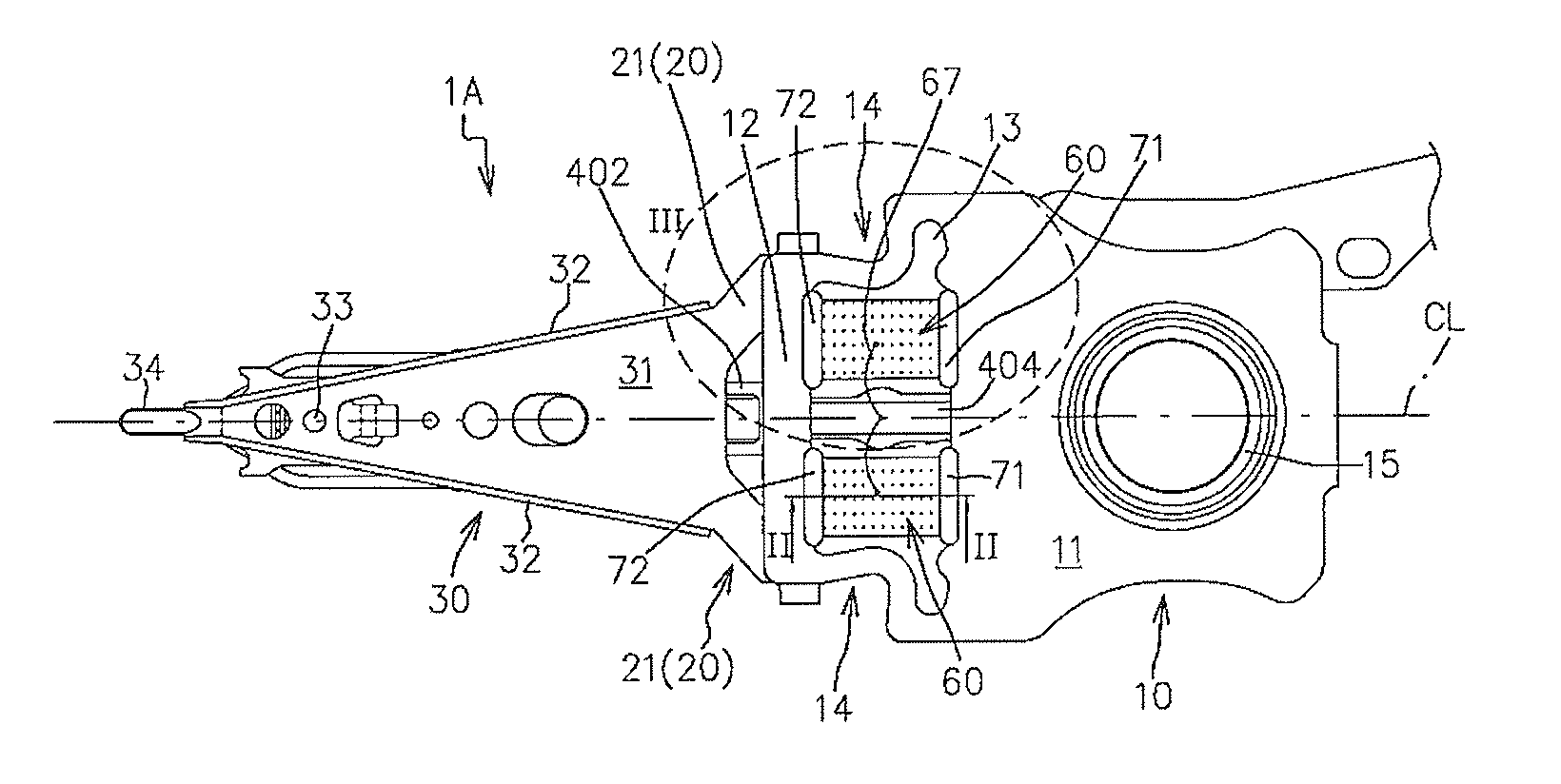
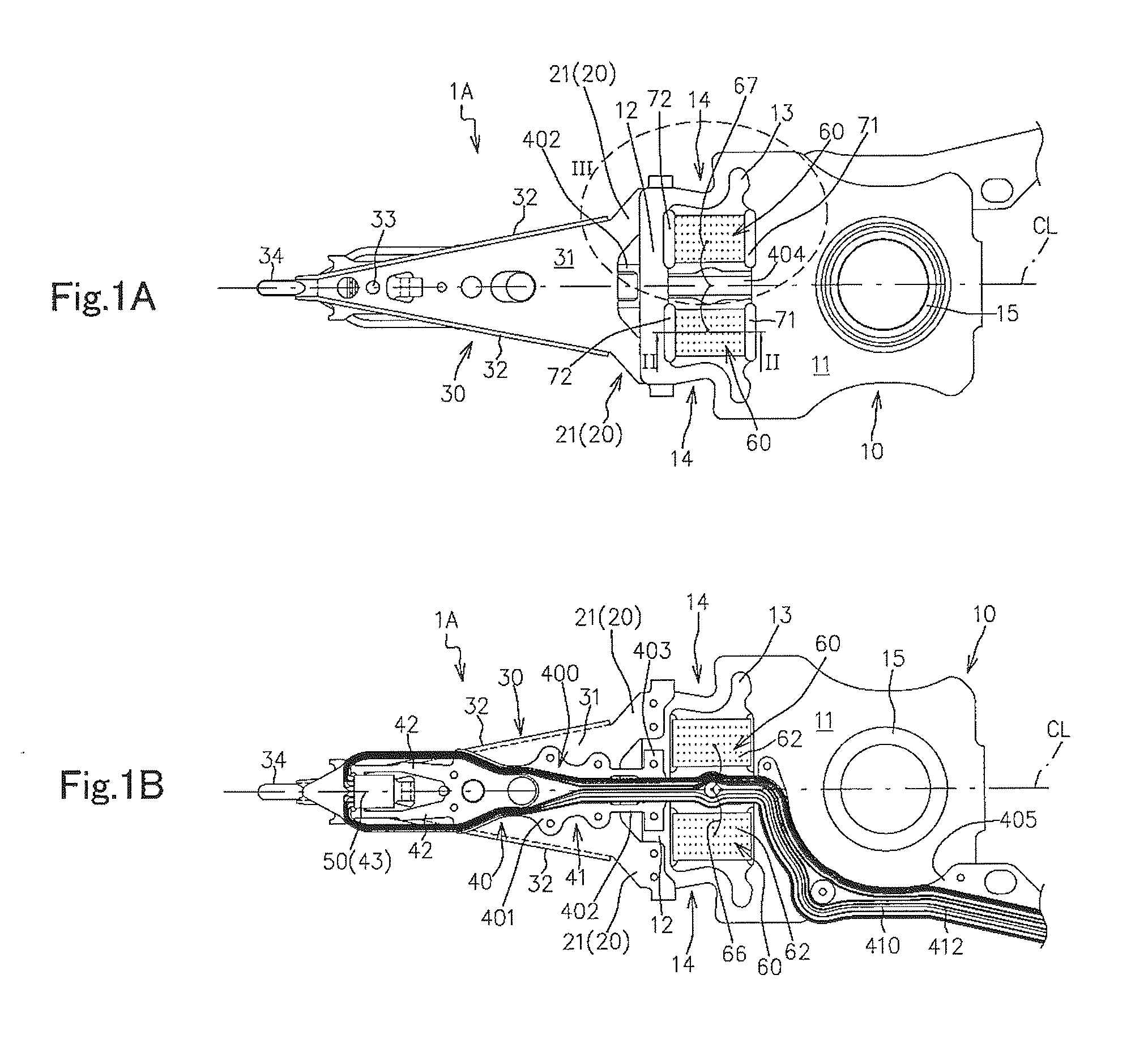
[0058]FIGS. 1A and 1B are a top view (a plan view as viewed from a side opposite from a disk surface) and a bottom view (a bottom plan view as viewed from a side close to the disk surface) of a magnetic head suspension 1A according to the present embodiment, respectively. FIG. 1B indicates welding points with using small circles.
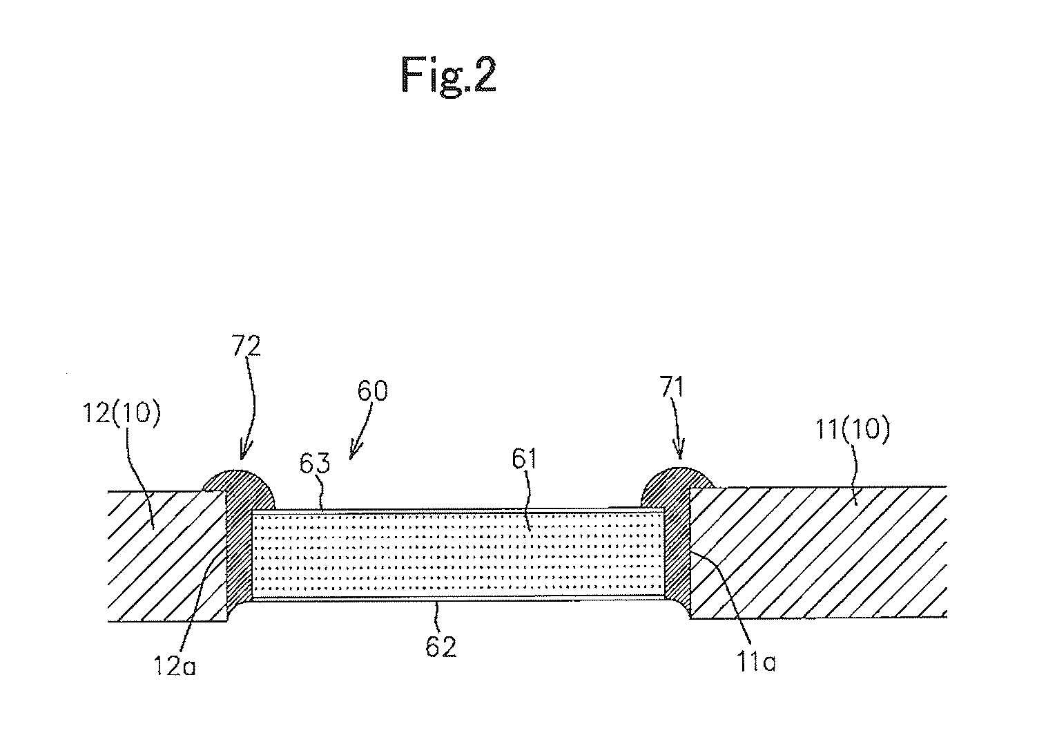
[0059]FIG. 2 is a cross sectional view taken along line II-II in FIG. 1A.
[0060]As shown in FIGS. 1A and 1B, the magnetic head suspension 1A includes a load bending part 20 that generates a load for pressing a magnetic head slider 50 toward a disk surface, a load beam part 30 that transmits the load to the magnetic head slider 50, a supporting part 10 that supports the load beam part 30 via the load bending part 20 and is swung about a swing center in a seek direction parallel to the disk surfa...
second embodiment
[0141]Hereinafter, another embodiment of the magnetic head suspension according to the present invention will be described, with reference to the attached drawings.
[0142]FIGS. 7A and 7B are a top view and a bottom view of a magnetic head suspension 2A according to the present embodiment. FIG. 7B indicates welding points with using small circles.
[0143]FIGS. 8A and 8B are cross sectional views taken along line VIII(a)-VIII(a) and line VIII(b)-VIII(b) in FIG. 7A, respectively.
[0144]In the figures, the members same as those in the first embodiment are denoted by the same reference numerals to omit the detailed description thereof.
[0145]Furthermore, FIG. 9A is a top view of the magnetic head suspension 2A in a state where the paired piezoelectric elements 60 and the insulative adhesive agents 70 are removed therefrom, and FIG. 9B is a top view of a flexure part 40B of the magnetic head suspension 2A. FIG. 9A shows the paired piezoelectric elements 60 with a dashed line.
[0146]As shown in ...
third embodiment
[0184]Hereinafter, still another embodiment of the magnetic head suspension according to the present invention will be described, with reference to the attached drawings.
[0185]FIG. 13 is a top view of a magnetic head suspension 3A according to the present embodiment.
[0186]FIGS. 14A and 14B are cross sectional views taken along line XIV(a)-VIV(a) and line XIV(b)-XIV(b) in FIG. 13, respectively.
[0187]In the figures, the members same as those in the first and second embodiments are denoted by the same reference numerals to omit the detailed description thereof.
[0188]As shown in FIGS. 13, 14A and 14B, the magnetic head suspension 3A according to the present embodiment is different from the magnetic head suspension 2A mainly in that the supporting part 10 is replaced with a supporting part 10C.
[0189]FIG. 15 is a top view of the supporting part 10C.
[0190]As shown in FIGS. 13 and 15, the supporting part 10C includes the components of the supporting parts 10, 10B, and also includes a centra...
PUM
| Property | Measurement | Unit |
|---|---|---|
| thickness | aaaaa | aaaaa |
| thick | aaaaa | aaaaa |
| thickness | aaaaa | aaaaa |
Abstract
Description
Claims
Application Information
 - R&D
- Intellectual Property
- Life Sciences
- Materials
- Tech Scout
- Unparalleled Data Quality
- Higher Quality Content
- 60% Fewer Hallucinations
Browse by: Latest US Patents, China's latest patents, Technical Efficacy Thesaurus, Application Domain, Technology Topic, Popular Technical Reports.
© 2025 PatSnap. All rights reserved.Legal|Privacy policy|Modern Slavery Act Transparency Statement|Sitemap|About US| Contact US: help@patsnap.com


