Fiber optic splitter module

Active Publication Date: 2011-03-10
COMMSCOPE TECH LLC
View PDF60 Cites 30 Cited by
  • Summary
  • Abstract
  • Description
  • Claims
  • Application Information

AI Technical Summary

Problems solved by technology

While the chassis may accept several modules, the initial installation may only include fewer modules mounted in the chassis, or enough

Method used


Image

  • Fiber optic splitter module
  • Fiber optic splitter module
  • Fiber optic splitter module

Examples


Embodiment Construction

[0059]Reference will now be made in detail to exemplary aspects of the present invention which are illustrated in the accompanying drawings. Wherever possible, the same reference numbers will be used throughout the drawings to refer to the same or similar parts.

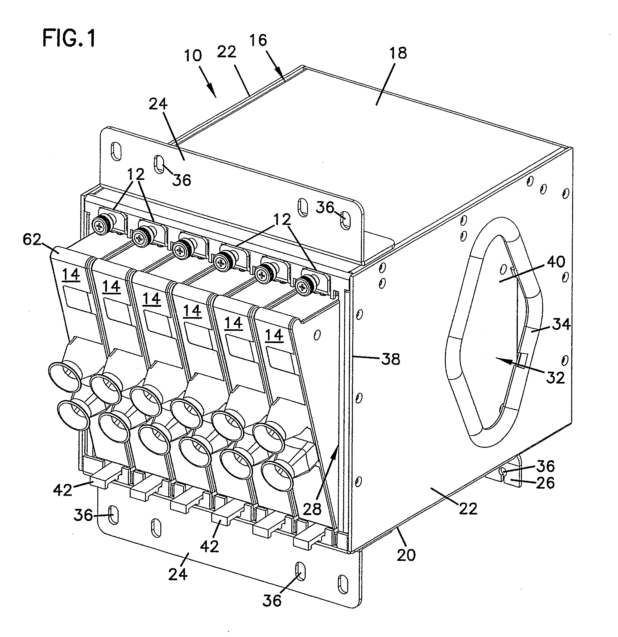
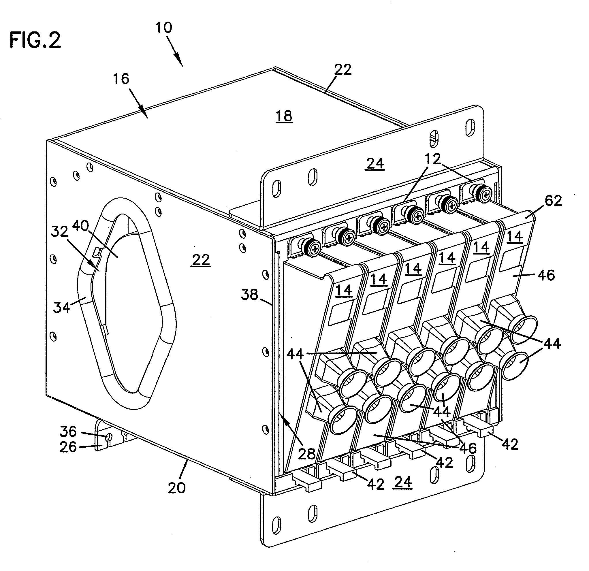
[0060]FIG. 1 illustrates a telecommunications assembly 10 with mounting locations 12 for mounting a plurality of modules 14. Assembly 10 includes a chassis or housing 16 with a first major side 18, a second major side 20 and a pair of opposing transverse sides 22 extending between the first and second major sides. A mounting flange 24 may be mounted to each of the major sides extending generally oppositely of each other. A secondary or alternative mounting flange 26 may also be mounted to one of the major sides to provide options for mounting housing 16 to a particular size or shape of equipment rack, cabinet or other type of installation.

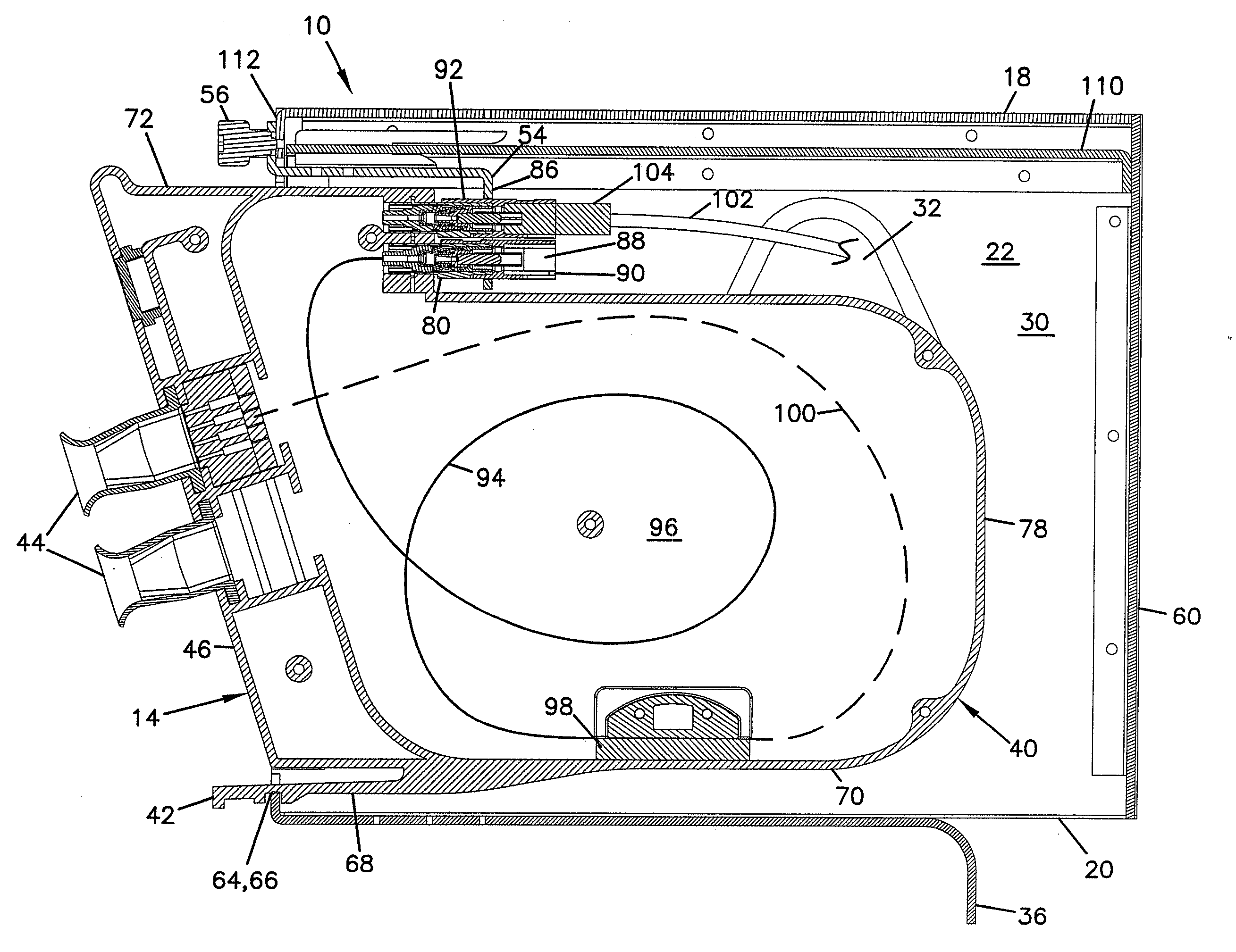
[0061]Housing 16 defines a front opening 28 through which modules 14 are inserted within...


PUM


Abstract

A telecommunications assembly including a housing and a plurality of modules mounted within the housing. The modules includes a rear face in which is mounted at least one fiber optic connector. Within an interior of the housing are positioned at least one fiber optic adapters. Inserting the module through a front opening of the housing at a mounting location positions the connector of the module for insertion into and mating with the adapter of the housing. The adapters within the interior of the housing are integrally formed as part of a removable adapter assembly. A method of mounting a telecommunications module within a chassis.

Description

CROSS REFERENCE TO RELATED APPLICATIONS[0001]This application is a continuation of application Ser. No. 12 / 150,313, filed Apr. 24, 2008, which is a continuation of application Ser. No. 11 / 138,063, filed May 25, 2005, now U.S. Pat. No. 7,400,813, which applications are incorporated herein by reference in its entirety.FIELD[0002]The present invention generally relates to fiber optic telecommunications equipment. More specifically, the present invention relates to fiber optic modules and chassis for holding fiber optic modules.BACKGROUND[0003]In fiber optic telecommunications systems, it is common for optical fibers of transmission cables to be split into multiple strands, either by optical splitting of a signal carried by a single stranded cable or by fanning out the individual fibers of a multi-strand cable. Further, when such systems are installed, it is known to provide excess capacity in the installations to support future growth and utilization of the fibers. Often in these insta...

Claims


Application Information

Patent Timeline
IPC IPC(8): G02B6/00
CPCG02B6/3825G02B6/4455G02B6/3897G02B6/46G02B6/38
Inventor ZIMMEL, STEVEN C.
Owner COMMSCOPE TECH LLC
Why Eureka
Try Eureka