
Rotary compressor and method

Inactive Publication Date: 2011-03-10
CAIRE
View PDF7 Cites 19 Cited by
  • Summary
  • Abstract
  • Description
  • Claims
  • Application Information

AI Technical Summary

Benefits of technology

[0007]An aspect of the present disclosure involves a rotary compressor that is primarily optimized for use without the need for liquid lubricants, such as in the flow path of the fluid being compressed. The compressors described herein are efficient, run quietly, use less power, and last longer than those previously known in the art. The compressors are useful for medical applications and other clean gas applications, for instance, where lubricants could contaminate the fluid being compressed and / or increased noise and / or vibration may be problematic. A specific example being medical respiratory applications, such as, pressure-swing-absorption and vacuum-pressure-swing-absorption oxygen concentrators. The usefulness of the compressors described herein is not limited to traditional clean gas applications. For example, the lubricating oil used in refrigeration compressors coats the inside surfaces of the heat exchangers in the refrigeration system. This reduces the effectiveness of the heat exchangers, which results in a decrease in system efficiency. Use of the disclosed compressor technology in refrigeration systems could improve the efficiency of these systems.
[0013]In certain instances, a rotary compressor of the disclosure does not have a fluid lubricant other than the process fluid within contact of the chamber. For instance, for the purpose of increasing the efficiency of compressor function.

Problems solved by technology

The compressors are useful for medical applications and other clean gas applications, for instance, where lubricants could contaminate the fluid being compressed and / or increased noise and / or vibration may be problematic.
This reduces the effectiveness of the heat exchangers, which results in a decrease in system efficiency.

Method used


Image

  • Rotary compressor and method
  • Rotary compressor and method
  • Rotary compressor and method

Examples


Embodiment Construction

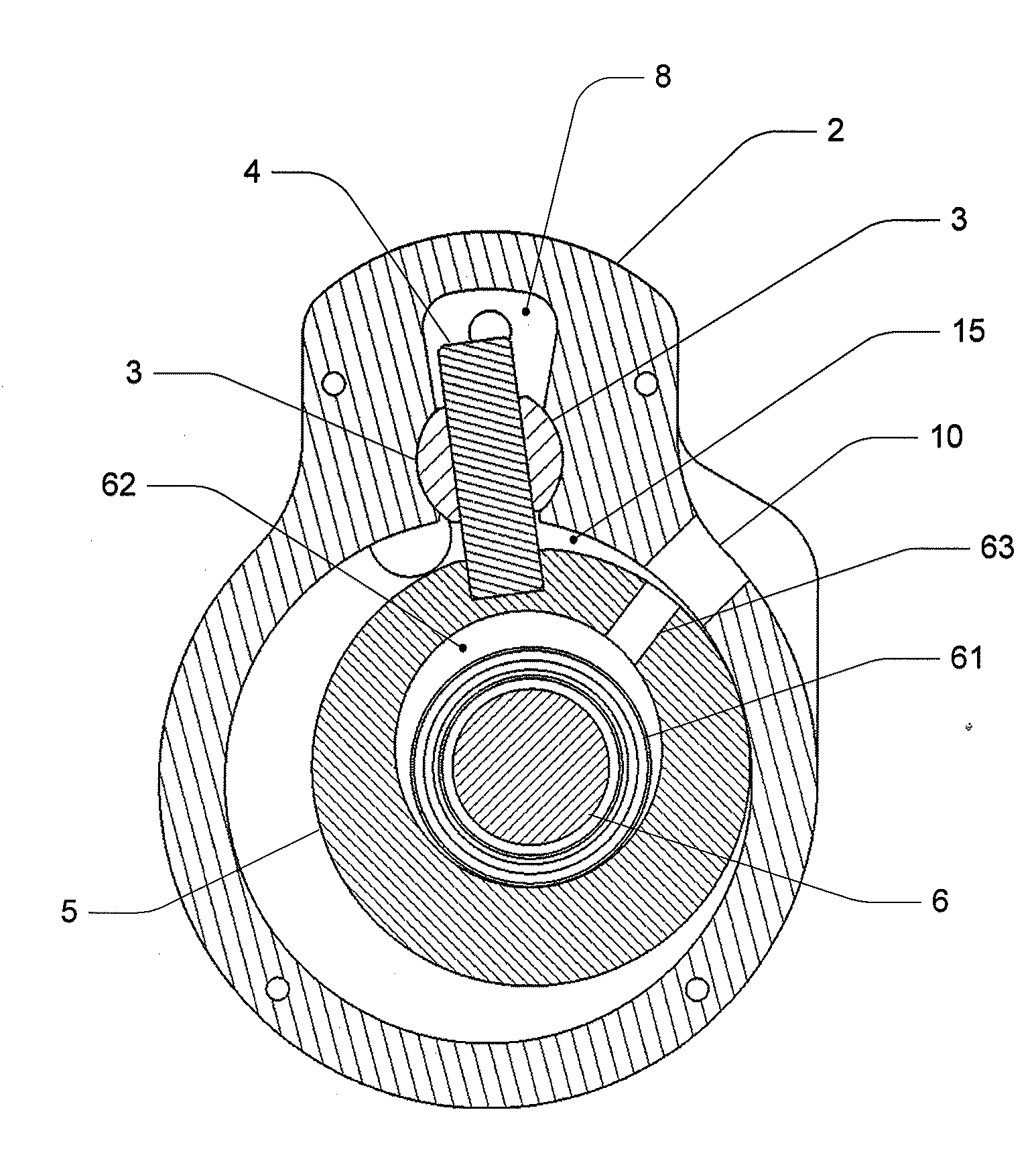
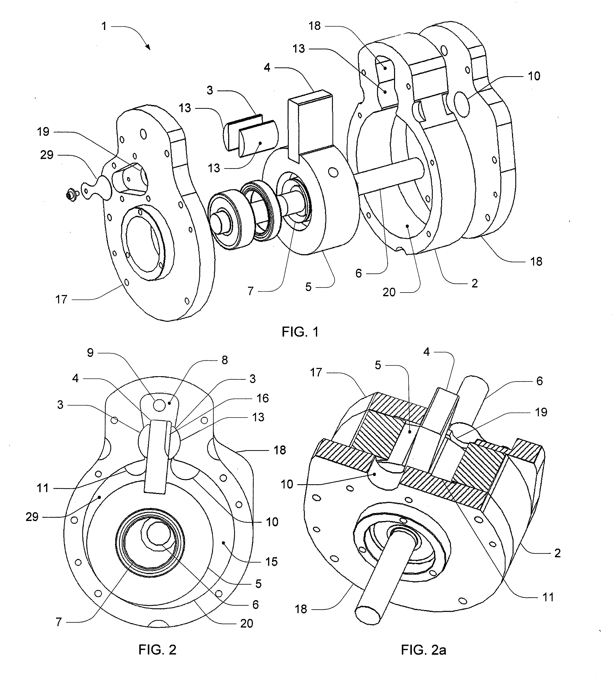
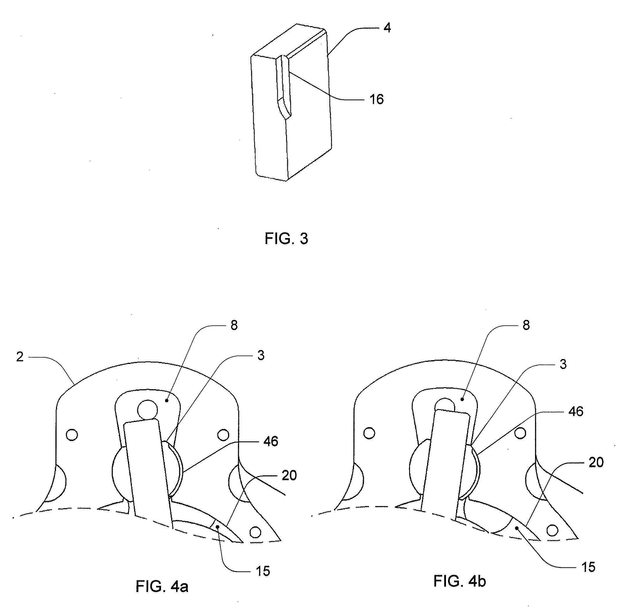
[0056]With reference to FIGS. 1-25b, multiple embodiments of a rotary compressor and method will be shown and described.

[0057]FIG. 1 shows an exploded view of a rotary compressor 1. An exemplary rotary compressor 1 of the disclosure includes several inter-related parts.

[0058]For instance, the compressor includes a housing. The housing may be formed as a stator 2 and may include two endplates, for instance, a discharge end plate 17 and a suction end plate 18. As depicted, the discharge end plate 17 includes a discharge port 19, and the suction endplate 18 includes a suction port 10. It is to be noted that although the discharge and suction ports are depicted herein as being associated with respective endplates, in other embodiments, one or both ports may be associated with a single endplate or other parts of the compressor housing. Also, it is to be noted that although the endplates are depicted as separate components from the housing, an endplate can be an integral part of the housi...


PUM


Abstract

An aspect of the present disclosure involves a rotary compressor that is primarily optimized for use without the need for liquid lubricants, such as in the flow path of the fluid being compressed, and is efficient and quiet to use. The compressors described herein are efficient, run quietly, use less power, and last longer than those previously known in the art. The compressors are useful for medical applications and other clean gas applications, for instance, where lubricants could contaminate the fluid being compressed and / or increased noise and / or vibration may be problematic.

Description

[0001]This application claims priority under 35 U.S.C. §119(e) of co-pending U.S. Provisional Patent Application Ser. No. 61 / 241,331, entitled “Rotary Compressor and Method,” filed Sep. 10, 2009. Priority of the filing date of Sep. 10, 2009, is hereby claimed, and the disclosure of the provisional patent application is hereby incorporated by reference in its entirety.[0002]The technology presented herein relates to rotary compressors.[0003]U.S. Pat. No. 993,530 and U.S. Pat. No. 2,313,387 disclose rotary compressors. Compressors configured in this manner are commonly used as vacuum pumps and as refrigeration compressors. Liquid lubricants perform several functions within a compressor. Lubricants reduce the friction between contacting components that are in relative motion with respect to one another. This reduces frictional heating and wear. For instance, surrounding the compression space of a compressor small leakage paths exist between adjacent parts that allow compressed gas at a...

Claims


Application Information

Patent Timeline
IPC IPC(8): F04C2/356F04C23/00
CPCF01C21/104F04C18/322F04C18/3564F04C29/02F04C23/001F04C2230/91F04C18/38
Inventor HUGENROTH, JASON JAMES
Owner CAIRE
Learn More