Filter Assembly with Modular Relief Valve Interface
a technology of filter assembly and relief valve, which is applied in the direction of filtration separation, separation process, membrane technology, etc., can solve the problems of filter canister replacement, restrict or close the path used by flowing fuel, and plug or block the porous holes in the filter media
- Summary
- Abstract
- Description
- Claims
- Application Information
AI Technical Summary
Benefits of technology
Problems solved by technology
Method used
Image
Examples
second embodiment
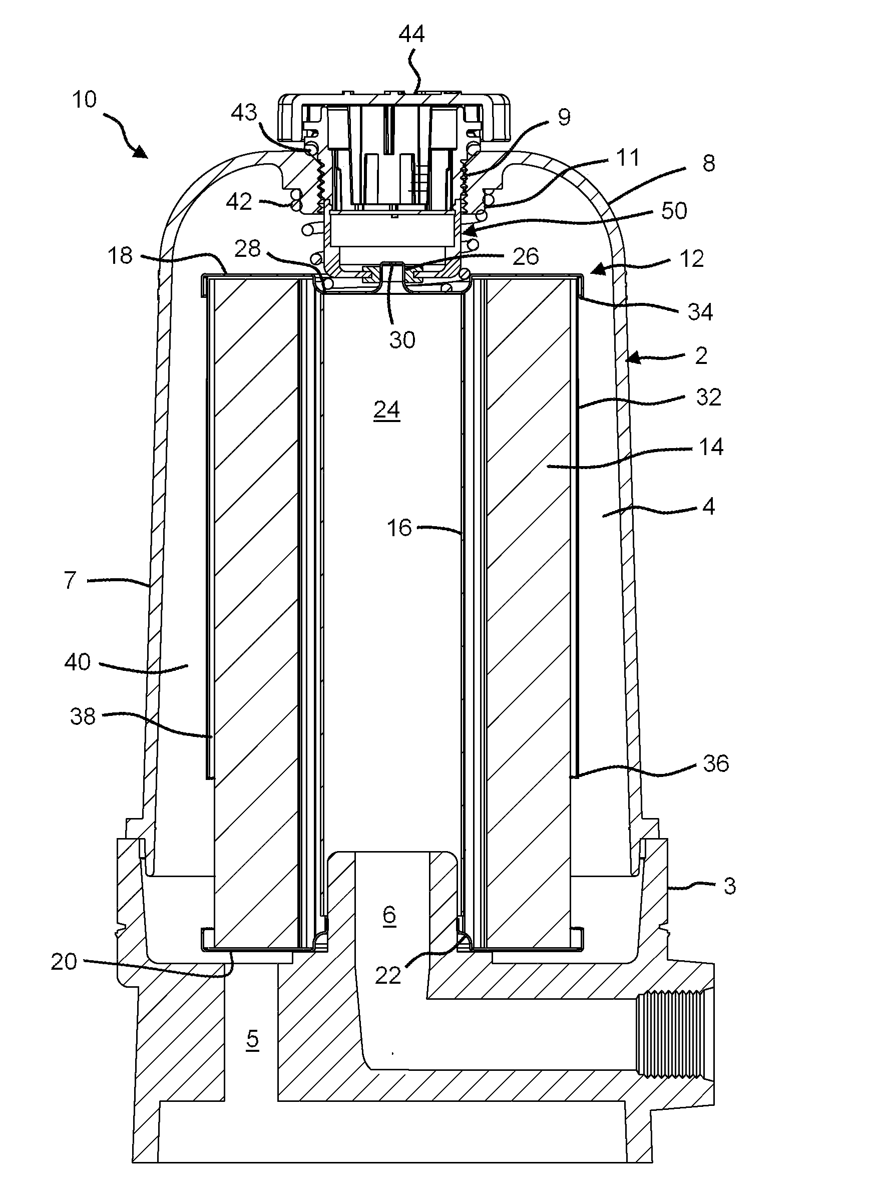
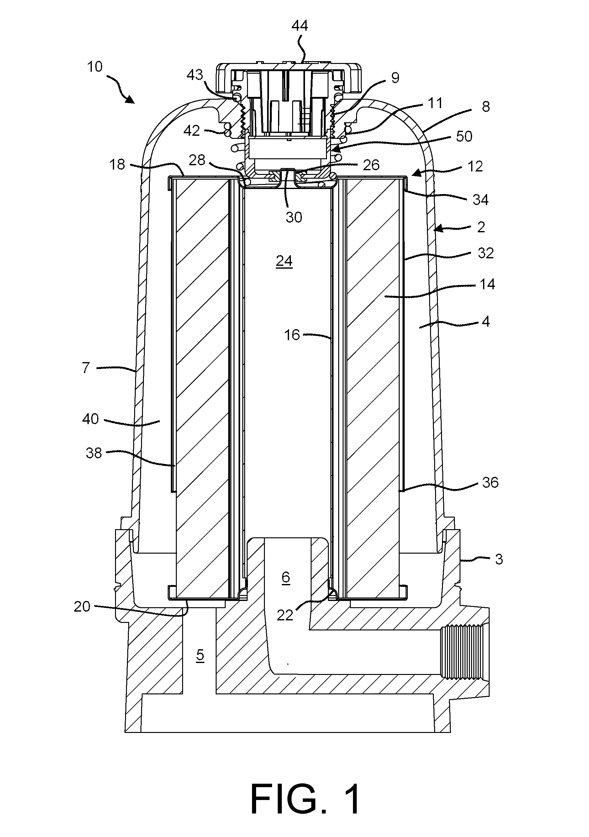
[0059]FIGS. 5-7 show the fluid filter assembly 10, which includes an alternative pressure relief structure 150. The pressure relief structure 150 is similar to the pressure relief structure 50 described in connection with FIG. 1, except as noted herein. So that the pressure relief structure 150 may urge the fluid filter 10 into engagement with the base portion 3 of the fluid filter assembly 10, the length of a housing 152 of the pressure relief structure 150 is selected to completely occupy the vertical space between the vent cap 44 and the top end cap 18 of the fluid filter 12 when the fluid filter 12 is firmly seated upon the base portion 3. In order to provide a seal between the housing 152 of the pressure relief structure 150 and the filter element 12, an annular face seal 157 is provided on a lower end 156 of the housing 152 and extends into a filter interface passage 155 of the housing 152. The annular face seal 157 is configured to be received within the circular trough 28 th...
third embodiment
[0061]FIG. 8 shows the fluid filter assembly 10, wherein a fluid filter assembly 200 having a divider 232 is connected to or formed integrally with an upright housing 202 thereof. The fluid filter assembly 200 may be used in conjunction with a pressure relief structure 50, as shown in FIG. 1, a pressure relief structure 150, as shown in FIG. 5, or with a pressure relief structure 50 that is provided as a portion of the fluid filter 12.
[0062]As best seen in FIGS. 8 and 9, the divider 232 is generally cylindrical in shape, having a sidewall 242 that creates a generally tubular shape for the divider 232 below an axial end cap 244 of the divider 232. A central aperture 246 is defined through the axial end cap 244. An annular sealing ring 248 surrounds the aperture 246 and is located on the interior of the divider 232 in order to create a seal between the divider 232 and the fluid filter 12. A plurality of ribs 250 are arrayed circumferentially around the side walls 242 and axial end pla...
PUM
| Property | Measurement | Unit |
|---|---|---|
| pressure | aaaaa | aaaaa |
| torque | aaaaa | aaaaa |
| interface structure | aaaaa | aaaaa |
Abstract
Description
Claims
Application Information
 - R&D
- Intellectual Property
- Life Sciences
- Materials
- Tech Scout
- Unparalleled Data Quality
- Higher Quality Content
- 60% Fewer Hallucinations
Browse by: Latest US Patents, China's latest patents, Technical Efficacy Thesaurus, Application Domain, Technology Topic, Popular Technical Reports.
© 2025 PatSnap. All rights reserved.Legal|Privacy policy|Modern Slavery Act Transparency Statement|Sitemap|About US| Contact US: help@patsnap.com


