Illumination optical system and projection display apparatus
an optical system and projection display technology, applied in the direction of fixed installation, lighting and heating equipment, instruments, etc., can solve the problems of complicated illumination optical system, increased size, weight and manufacturing cost of the apparatus, and reduced luminous flux owing to irradiation so as to reduce the amount of luminous flux available on the outside of the display surface, the effect of reducing the non-uniformity of the illuminance distribution on the display surfa
- Summary
- Abstract
- Description
- Claims
- Application Information
AI Technical Summary
Benefits of technology
Problems solved by technology
Method used
Image
Examples
first exemplary embodiment
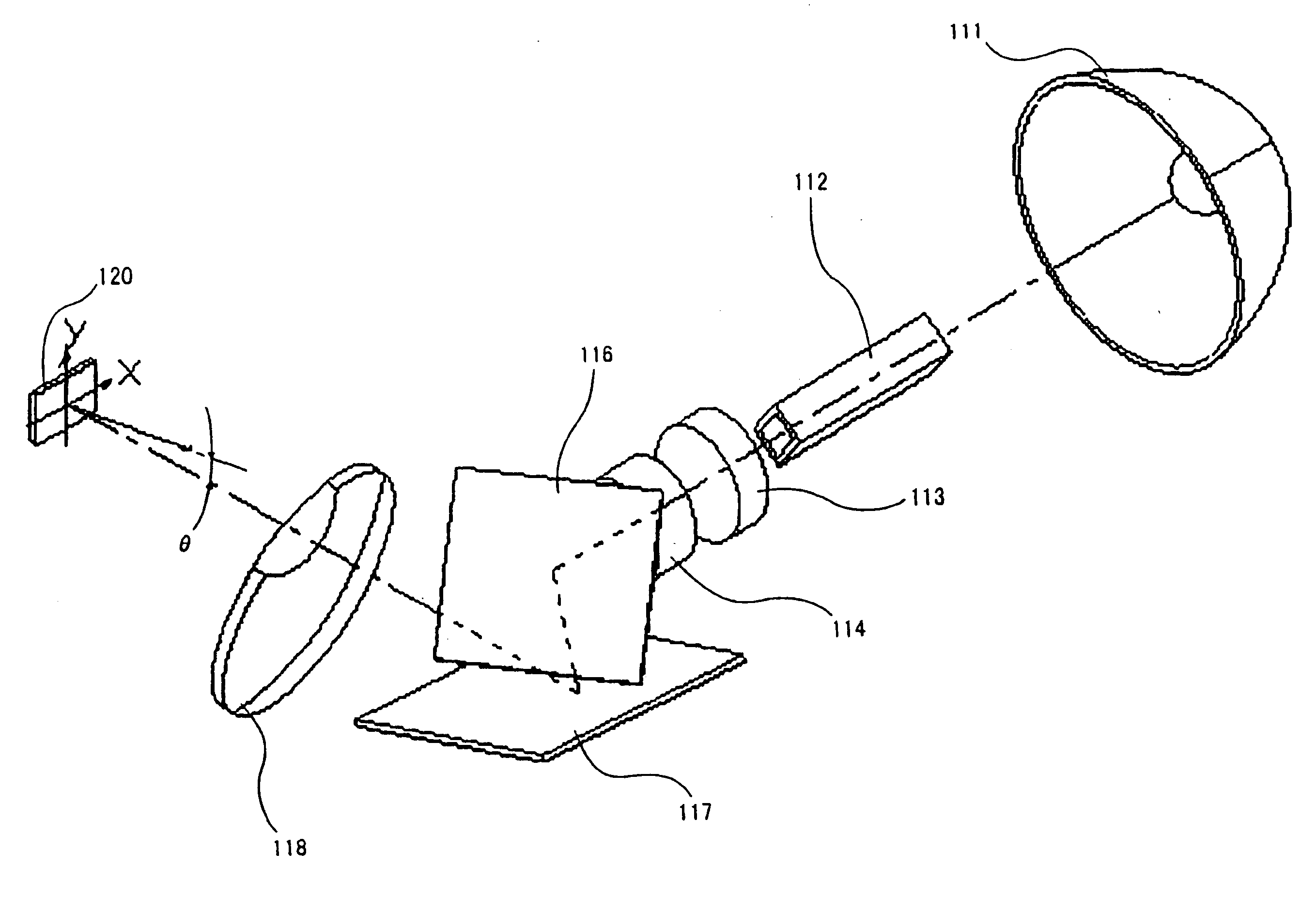
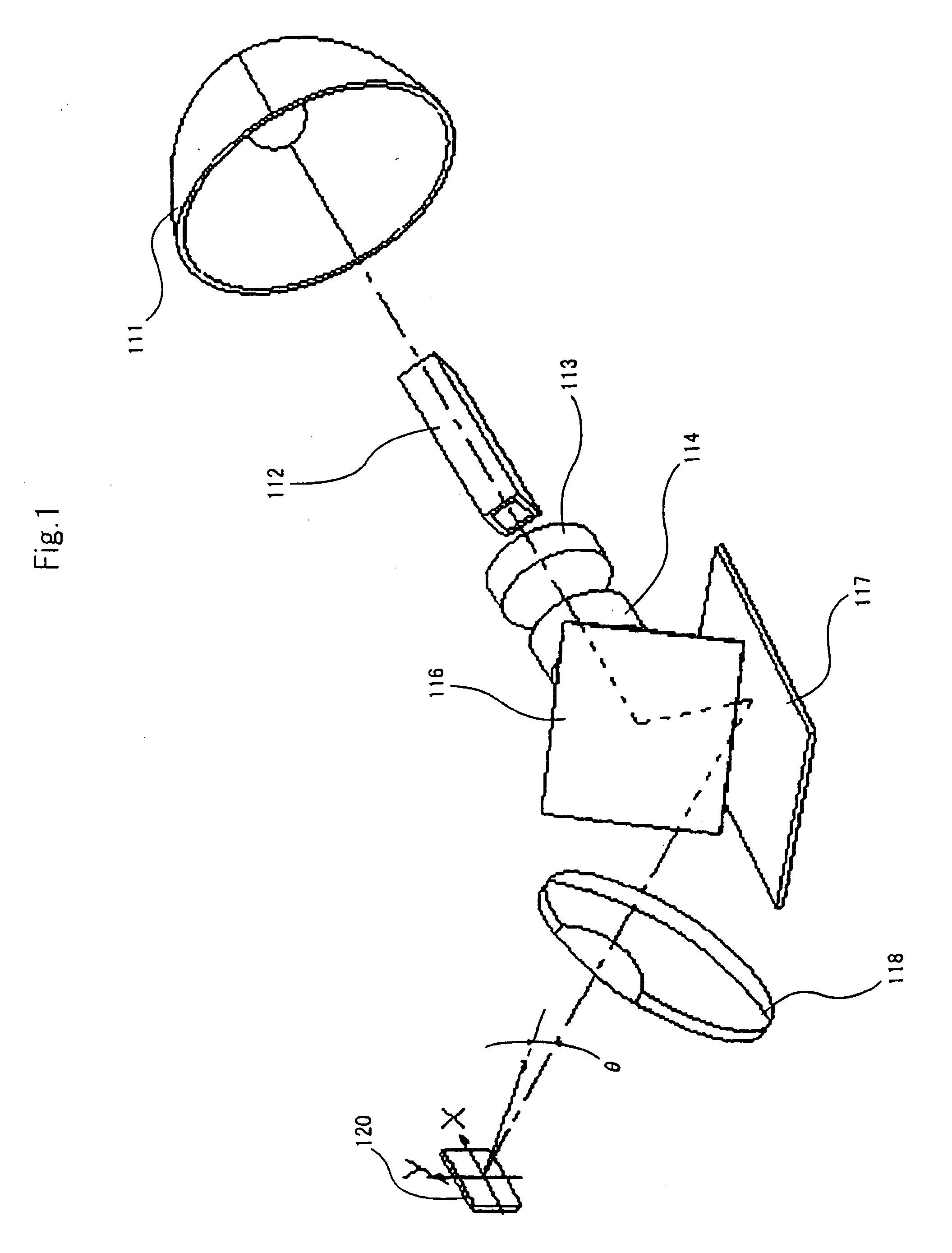
[0030]A projection display apparatus of a first exemplary embodiment includes a display element that modulates a luminous flux irradiating a display surface according to an image signal, an illumination optical system that guides a luminous flux from a light source to the display element such that the beam enters a display surface, and an imaging optical system that enlarges and projects the luminous flux modulated by the display element.
[0031]FIG. 6A shows the illumination optical system included in the projection display apparatus of the first exemplary embodiment. FIG. 6B is a perspective view showing the shape of a prism element.
[0032]As shown in FIG. 6A, the illumination optical system of this exemplary embodiment includes, sequentially on the optical path: light source 11 emitting illumination light; light tunnel 12 that uniformizes the illuminance distribution of the luminous flux incident from the light source and emits the uniformized beam; and optical elements for forming ...
second exemplary embodiment
[0046]FIG. 9A shows an illumination optical system included in a projection display apparatus of a second exemplary embodiment. In this exemplary embodiment, for the sake of the convenience, identical components to the components of the first exemplary embodiment are assigned with the identical symbols, and the description thereof will be omitted.
[0047]This exemplary embodiment is different from the first exemplary embodiment in that the optical axes of the first and second lenses of the first exemplary embodiment are shifted or turned with respect to the optical axis of the light tunnel.
[0048]As shown in FIG. 9A, optical axis 23a of first lens 23 are arranged so as to be displaced parallel to optical axis 12c of light tunnel 12. Further, optical axis 24a of second lens 24 is arranged so as to be inclined with respect to optical axis 12c of light tunnel 12 by turning in at least any one of the three axes.
[0049]Also in this exemplary embodiment, as with the first exemplary embodiment...
PUM
 Abstract
Description
Claims
Application Information
 - R&D
- Intellectual Property
- Life Sciences
- Materials
- Tech Scout
- Unparalleled Data Quality
- Higher Quality Content
- 60% Fewer Hallucinations
Browse by: Latest US Patents, China's latest patents, Technical Efficacy Thesaurus, Application Domain, Technology Topic, Popular Technical Reports.
© 2025 PatSnap. All rights reserved.Legal|Privacy policy|Modern Slavery Act Transparency Statement|Sitemap|About US| Contact US: help@patsnap.com


