Lens actuating module

a technology of actuating module and actuating module, which is applied in the field of actuating module, can solve the problems of difficult manufacture of actuating module, inability to completely solve, and negatively affect the performance of a product, and achieve the effect of simple structure and miniaturization

Active Publication Date: 2011-03-17
SAMSUNG ELECTRO MECHANICS CO LTD
View PDF2 Cites 25 Cited by
  • Summary
  • Abstract
  • Description
  • Claims
  • Application Information

AI Technical Summary

Benefits of technology

[0013]The present invention is intended to provide a lens actuating module, in which a to lens barrel in a camera module is moved by the contracted or extended amount of a shape memory alloy wire, thus realizing a simple structure and miniaturization.
[0014]Further, the present invention is intended to provide a lens actuating module, which prevents a lens barrel from leaning or rotating when the lens actuating module is actuated, thus improving the actuating reliability of the lens actuating module.

Problems solved by technology

Such a groove complicates the structure, causes the lens actuating module to be difficult to manufacture, and cannot completely solve displacement interference between the piezoelectric devices.
The length restriction of the driving rods 16 and 17 limits the lens transfer length, so that it negatively affects the performance of a product.
In addition to a space for the lens transfer length, an additional space for receiving driving elements is required, so that it is difficult to realize the miniaturization of an entire module.
Further, only one end of the lens is supported by each driving rod 16 or 17, so that the lens has asymmetric displacement when the lens actuating module is driven, thus leading to unstable driving.

Method used


Image

  • Lens actuating module
  • Lens actuating module
  • Lens actuating module

Examples


first embodiment

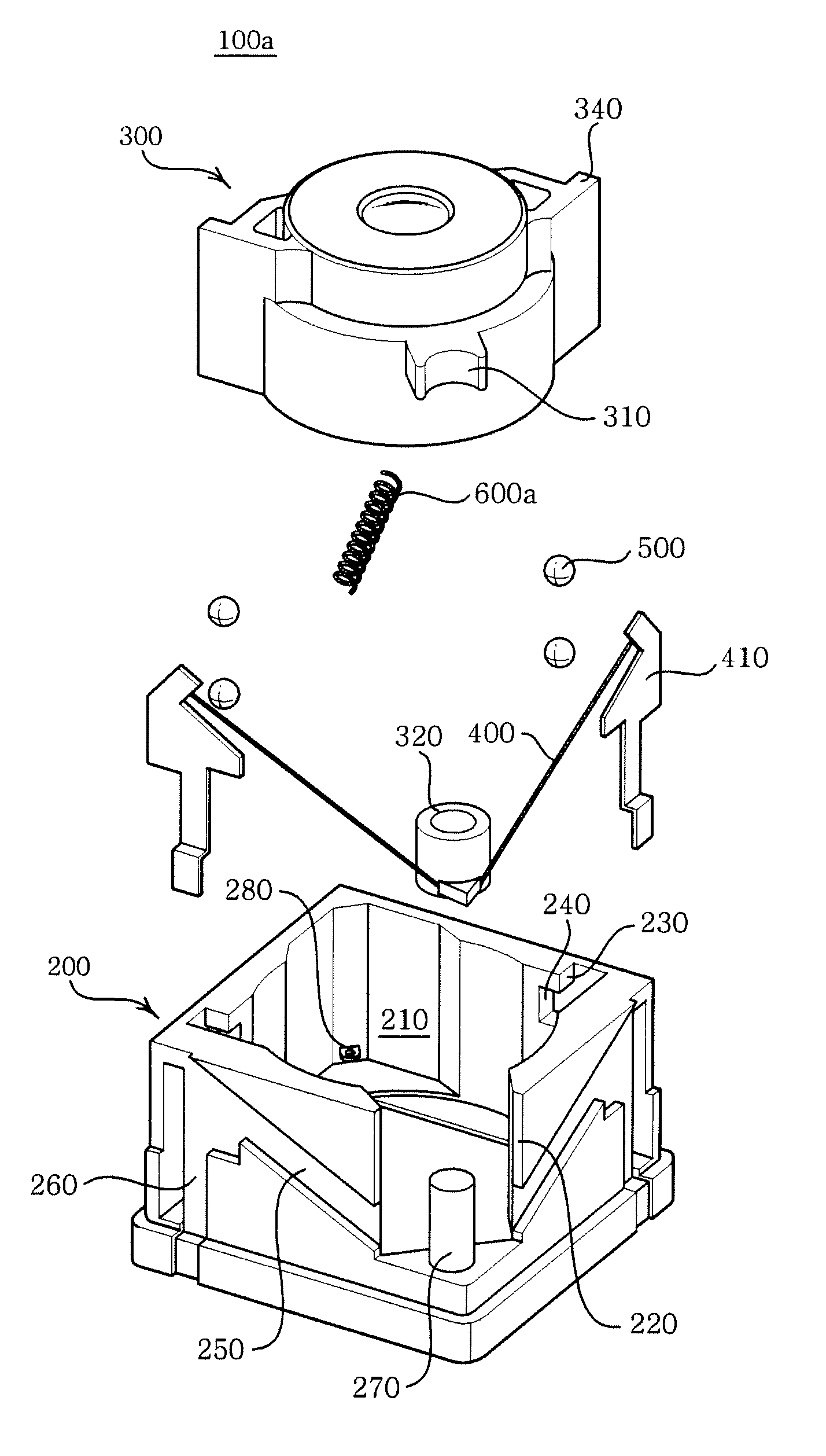
[0040]FIG. 3 is an exploded perspective view illustrating a lens actuating module according to a first embodiment of the present invention, FIG. 4 is a perspective view illustrating the assembled state of the lens actuating module of FIG. 3, and FIG. 5 is a plan view illustrating the assembled state of the lens actuating module of FIG. 3. Hereinafter, the lens actuating module 100a according to this embodiment will be described with reference to the accompanying drawings.

[0041]As shown in FIGS. 3 to 5, the lens actuating module 100a according to this embodiment includes a housing 200, a lens barrel 300 installed in the housing 200, a driving unit for actuating the lens barrel 300 in the direction of an optical axis using a shape memory alloy (SMA) wire 400, rotary members 500, and a preload unit 600a.

[0042]The housing 200 serves to provide a space for accommodating the lens barrel 300, and is constructed so that its upper end is open and an accommodating space 210 having a shape co...

second embodiment

[0062]FIG. 6 is an exploded perspective view illustrating a lens actuating module according to a second embodiment of the present invention, FIG. 7 is a perspective view illustrating the assembled state of the lens actuating module of FIG. 6, and FIG. 8 is a plan view illustrating the assembled state of the lens actuating module of FIG. 6. Since the second embodiment is identical with the first embodiment except for the construction of a preload unit 600b, elements common to both the embodiments will carry the same to reference numerals and duplicate descriptions will be omitted herefrom. Hereinafter, a lens actuating module 100b according to this embodiment will be described with reference to the accompanying drawings.

[0063]As shown in FIGS. 6 to 8, the preload unit 600b of the lens actuating module 100b according to this embodiment includes a magnet 610b, a yoke 620b, and elastic members 630b. The magnet 610b is provided on the inner circumference of the housing 200. The yoke 620b...

third embodiment

[0067]FIG. 9 is an exploded perspective view illustrating a lens actuating module according to a third embodiment of the present invention, FIG. 10 is a perspective view illustrating the assembled state of the lens actuating module of FIG. 9, and FIG. 11 is a plan view illustrating the assembled state of the lens actuating module of FIG. 9. Since the third embodiment is identical with the above-mentioned embodiments except for the construction of a preload unit 600b for the lens barrel, elements common to the embodiments will carry the same reference numerals and duplicate descriptions will be omitted herefrom. Hereinafter, a lens actuating module 100c according to this embodiment will be described with reference to the accompanying drawings.

[0068]As shown in FIGS. 9 to 11, the lens actuating module 100c according to this embodiment uses a plate spring as an elastic member 630c unlike the lens actuating module 100b according to the second embodiment. Here, since the plate spring per...


PUM


Abstract

Disclosed herein is a lens actuating module. The module includes a housing having an accommodating space and a bush guide. A lens barrel is accommodated in the accommodating space and includes a lens and a barrel hook. A driving unit applies a driving force to a bush such that it is moved up in the direction of the optical axis, by pulling force of contraction of a shape memory alloy wire. The bush is guided by the bush guide and engages with the barrel hook. A rotary member is interposed between the housing and the lens barrel. A preload unit pulls the lens barrel in the direction of the optical axis such that the lens barrel moves down to an original position, and pulls the lens barrel in a direction perpendicular to the optical axis to maintain a contact of the lens barrel with the rotary member.

Description

CROSS REFERENCE TO RELATED APPLICATION(S)[0001]This application claims the benefit of Korean Patent Application No. 10-2009-0085953, filed on Sep. 11, 2009, entitled “Lens Actuating Module”, which is hereby incorporated by reference in its entirety into this application.BACKGROUND OF THE INVENTION[0002]1. Technical Field[0003]The present invention relates to a lens actuating module.[0004]2. Description of the Related Art[0005]Generally, personal portable terminals such as an electronic device, a mobile phone or a PDA have additional functions as well as a main function. Currently, many electronic devices additionally have a camera function, so that they appeal to consumers. Thus, a market for camera modules mounted on the electronic devices has been gradually expanding.[0006]In order to satisfy the demand of the market, the camera module has been developed to have additional functions including an auto-focusing function, an optical zoom function, and an Optical Image Stabilization (...

Claims


Application Information

Patent Timeline
Patent Type & Authority Applications(United States)
IPC IPC(8): G02B7/04
CPCG02B7/022G02B7/102G02B7/026G02B7/09
Inventor PARK, JAE HYUKKANG, BYUNG HOONHAN, CHUL YEUBHWANG, JUNG WOOKKO, HYUN PHILLLIM, SOO CHEOL
Owner SAMSUNG ELECTRO MECHANICS CO LTD
Why Eureka
Try Eureka