Method and device for casting a ring-shaped plastic frame in a recess of a rotor disk of a double-sided machining machine

a technology of rotor disk and ring, which is applied in the direction of lapping machines, manufacturing tools, other domestic articles, etc., can solve the problems such as the inability to control the desired manner of plastic frame alignment, rotor disk and plastic frame, and achieve the effect of reducing injection pressure, shortening flow paths, and ensuring the quality of the plastic fram

Active Publication Date: 2020-04-16
PETER WOLTERS GMBH
View PDF0 Cites 0 Cited by
  • Summary
  • Abstract
  • Description
  • Claims
  • Application Information

AI Technical Summary

Benefits of technology

The patent text describes a method for casting plastic materials in a rotor disk that is partially filled with a mold core. The mold core has a casting channel that is connected to a supply of plastic. The mold parts have rings that fit together to delimit a mold volume for the plastic frame. The plastic is then cast into this mold volume through the casting channel. The resulting cast plastic is stable and can be easily removed with the rotor disk. The method also uses a regular arrangement of feeders to improve the flow and venting of the plastic in the mold. This simplifies the process for minimizing the injection and holding pressure.

Problems solved by technology

With the known method, critical parameters such as the alignment of the plastic frame relative to the rotor disk main body, and hence a specific step height between the rotor disk and plastic frame, cannot be controlled in the desired manner.
This in turn causes an uneven curvature of the semiconductor wafer edges after machining and hence an impairment of the local flatness.
A spread of the frame dimensions, in particular the frame thickness occurring in known methods for producing plastic frames yield undesirable deviations in the dimensions of the semiconductor wafers machined in the machine.

Method used


Image

  • Method and device for casting a ring-shaped plastic frame in a recess of a rotor disk of a double-sided machining machine
  • Method and device for casting a ring-shaped plastic frame in a recess of a rotor disk of a double-sided machining machine
  • Method and device for casting a ring-shaped plastic frame in a recess of a rotor disk of a double-sided machining machine

Examples


Embodiment Construction

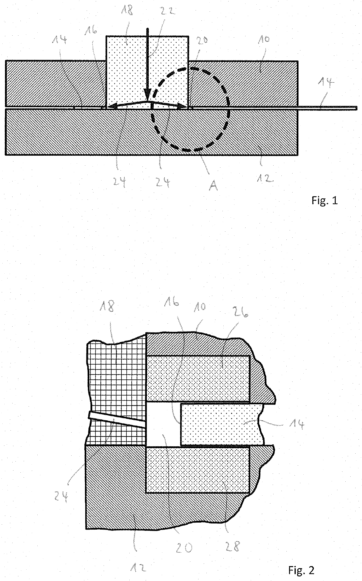
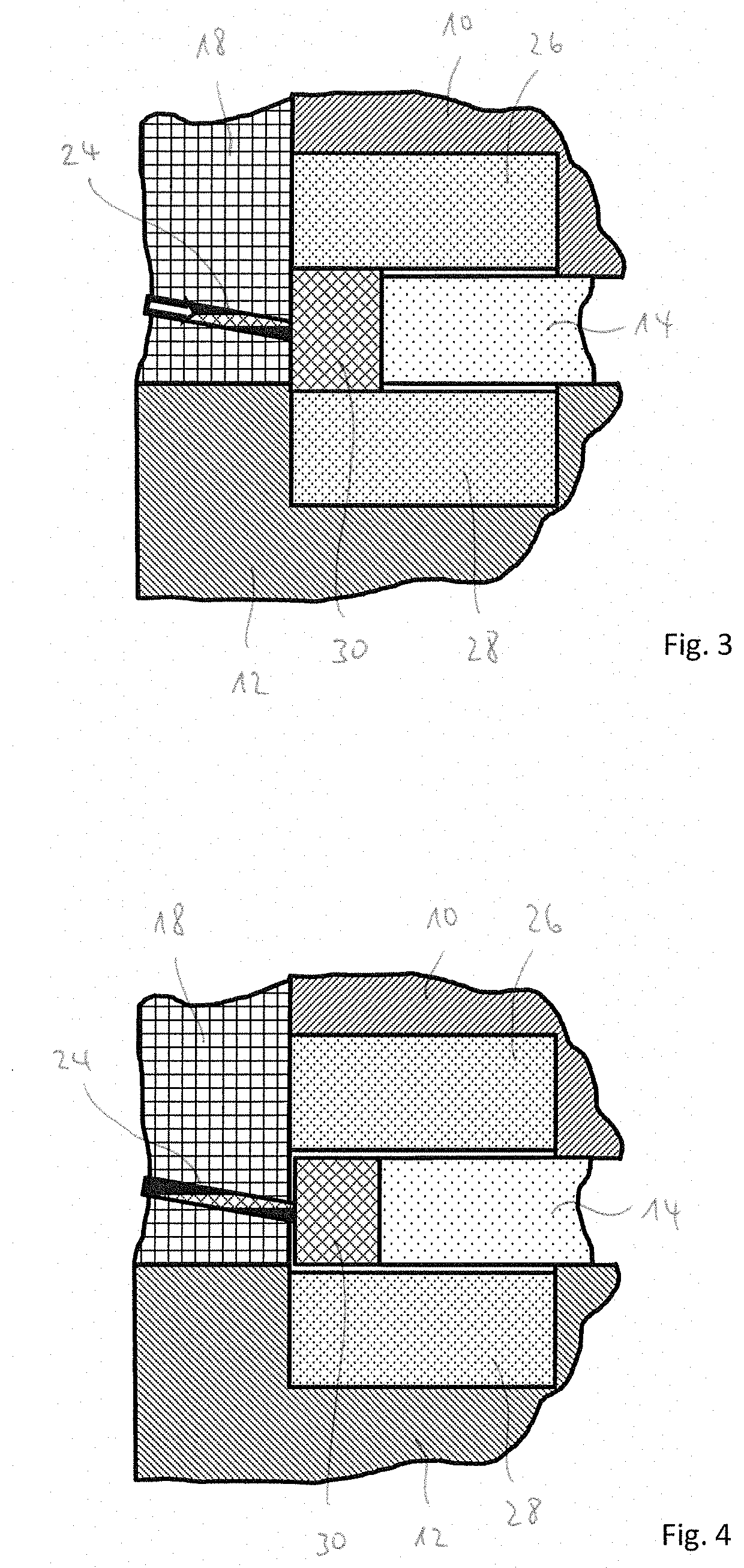
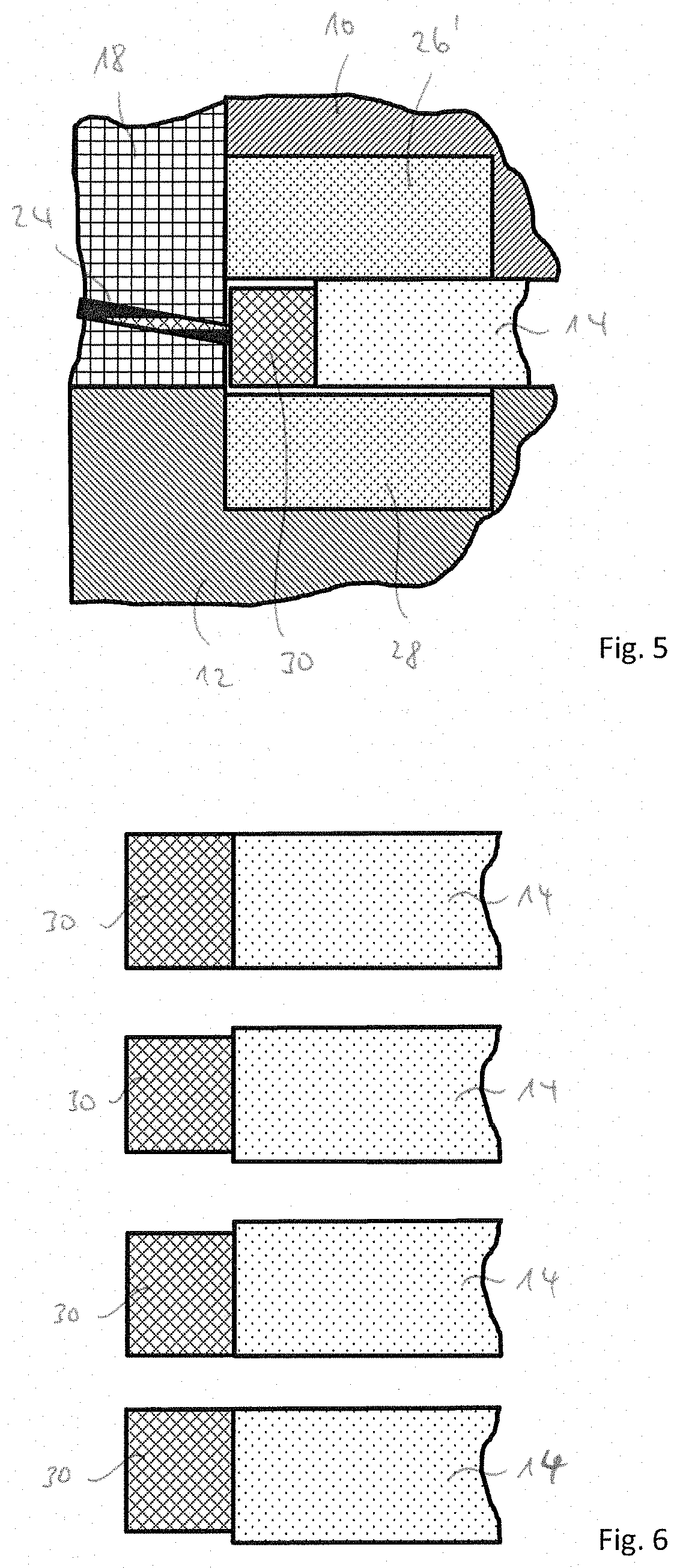
[0031]If not otherwise specified, the same reference numbers indicate the same objects in the figures. The device shown in FIG. 1 has a first mold part 10, in particular a first mold half, and a second mold part 12, in particular a second mold half A rotor disk 14 of a double-sided machining machine, in particular a double-sided polishing machine, is clamped between the mold parts 10, 12 and accordingly held. The rotor disk 14 possesses a plurality of for example circular recesses 16 of which one can be seen in FIG. 1. During operation, e.g. circular semiconductor wafers such as silicon wafers are held floating in the recesses 16 to be machined in a double-sided machining machine. The device shown in FIG. 1 furthermore has a mold core 18 which is inserted in the recess 16 and fills it up to a mold cavity 20. In one embodiment, the mold cavity 20 is ring-shaped. Reference signs 22, 24 schematically indicate casting channels formed in the mold core 18 in FIG. 1. At its top end in FIG....


PUM

PropertyMeasurementUnit
viscosityaaaaaaaaaa
volumeaaaaaaaaaa
plasticaaaaaaaaaa

Abstract

A method for casting a ring-shaped plastic frame comprises providing two mold parts, wherein at least one of the two molds parts includes at least one ring-shaped seat. Positioning a rotor disk between the two mold parts where the rotor disk comprises at least one annular recess. Engaging a mold core with at least a portion of each of the two mold parts. The mold core comprises at least one casting channel configured to attach at one end to a supply of plastified plastic. Inserting at least one mold insert into the at least one ring-shaped seat. A mold volume is defined by the at least one mold insert, the mold core and an edge of the at least one annular recess, wherein the mold volume is configured to fluidly connect with the at least one casting channel to receive plastified plastic to form a plastic frame.

Description

CROSS REFERENCE TO RELATED APPLICATION[0001]This application is a divisional application of U.S. Non-Provisional application Ser. No. 15 / 223,702, filed Jul. 29, 2016 and entitled METHOD AND DEVICE FOR CASTING A RING-SHAPED PLASTIC FRAME IN A RECESS OF A ROTOR DISK OF A DOUBLE-SIDED MACHINING MACHINE which claims the benefit and priority of German Patent Application No. 10 2015 112 527.7, filed Jul. 30, 2015, under relevant sections of 35 USC § 119, the entire contents of which are hereby incorporated by reference.BACKGROUND OF THE INVENTION[0002]The invention relates to a device for casting a ring-shaped plastic frame in a recess or annular recess of a rotor disk of a double-sided machining machine, The recess serves to hold a workpiece in the double-sided machining machine during the double-sided machining process. The device comprises two mold parts that accommodate the rotor disk between themselves, and a mold core that partially fills in the recess when the rotor disk is accommo...

Claims


Application Information

Patent Timeline
Patent Type & Authority Applications(United States)
IPC IPC(8): B29C39/26B29C39/38B29C39/10B29C33/30B29C45/14
CPCB29C33/306B29L2031/3481B29C39/265B29C45/14336B29C39/38B29C39/10B29K2705/00B24B37/08B29C39/26B29L2031/736B29C45/1418B29C45/1459B29C45/27B29D12/00
Inventor MOLLER, HELGEKANZOW, JURGEN
Owner PETER WOLTERS GMBH
Why Eureka
Try Eureka