
Optical connector

a technology of optical connectors and connectors, applied in the field of optical connectors, can solve the problems of difficult optical alignment of optical connectors with multiple platforms, likely misalignment, etc., and achieve the effect of reducing structural complexity and miniaturization

Active Publication Date: 2019-08-27
OPTICIS CO LTD
View PDF25 Cites 0 Cited by
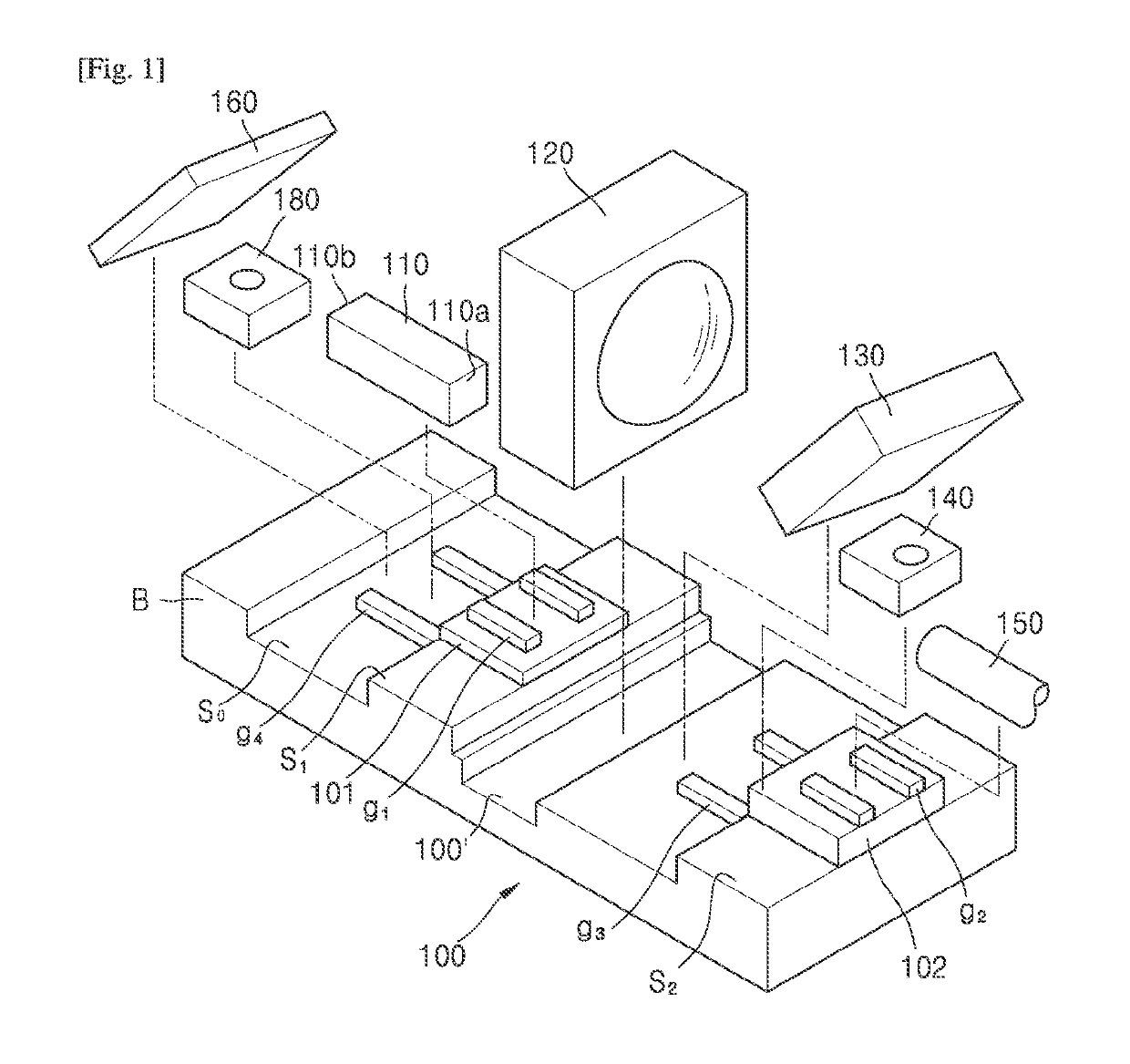
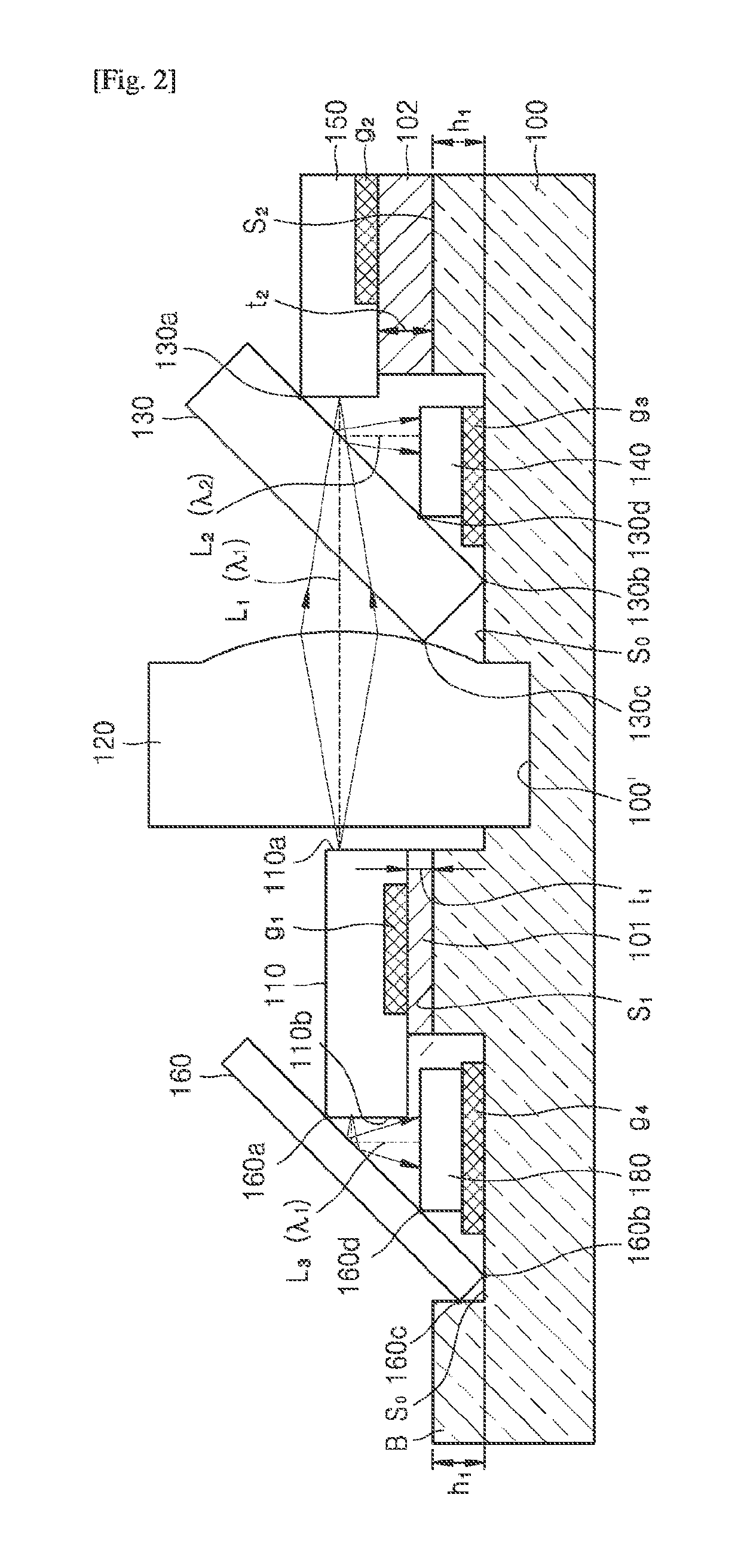
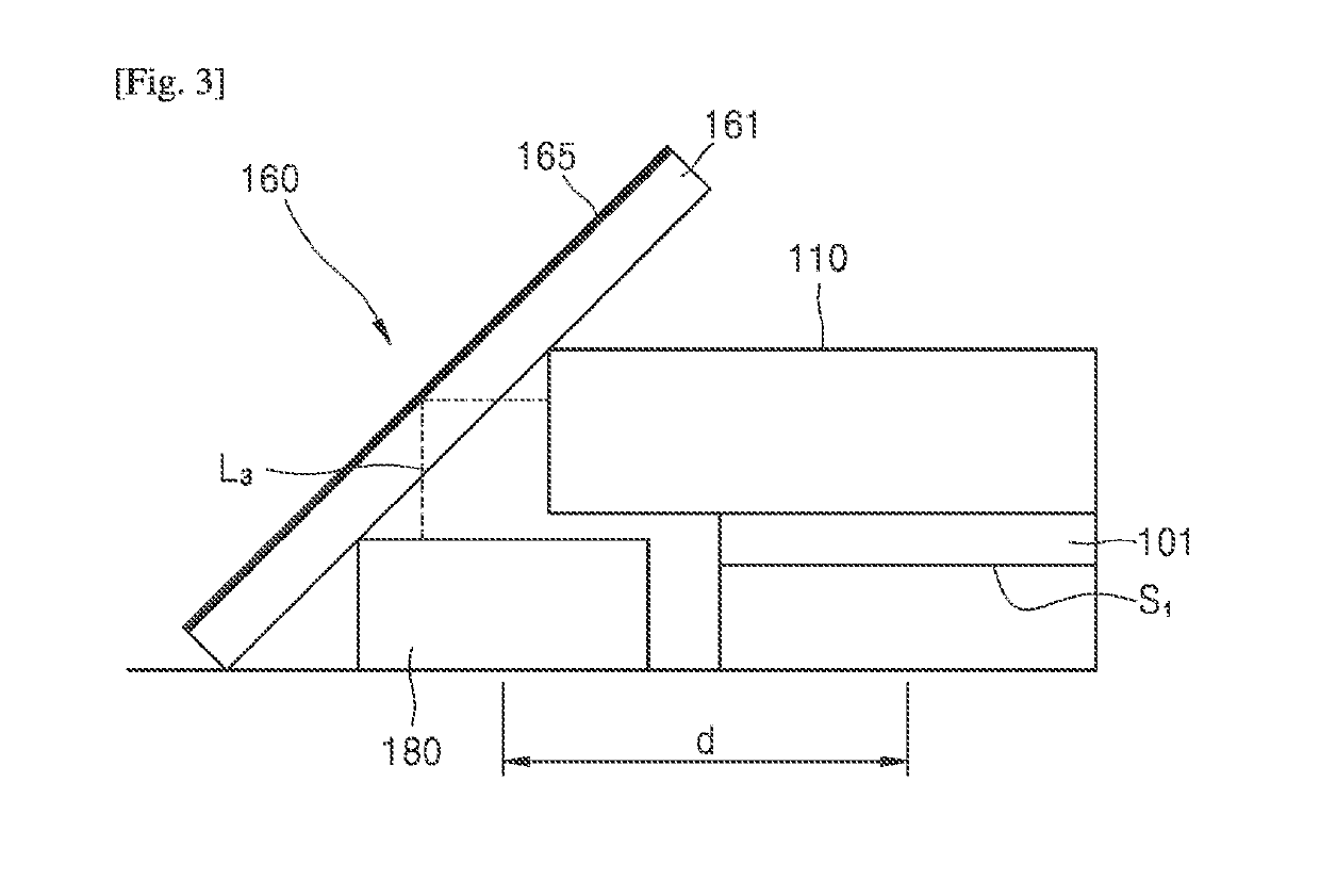
  • Summary
  • Abstract
  • Description
  • Claims
  • Application Information

AI Technical Summary

Benefits of technology

The present patent describes an optical connector that has a platform that automatically aligns the light emitting device, optical fiber, and optical components. This results in a simplified and smaller structure. The optical connector also has a guide wall that automatically aligns the light emitting device, optical fiber, light receiving device, and detection device. Overall, this optical connector has improved performance and efficiency.

Problems solved by technology

In an optical connector manufactured on the basis of such separate and different platforms, misalignment is likely to occur while optical components are optically aligned or while different support bases are integrated during alignment of optical components.
In particular, optical alignment of an optical connector having multiple different platforms is not easy in two-way communication for bidirectionally performing transmission and reception through one communication line.

Method used


Image

  • Optical connector
  • Optical connector
  • Optical connector

Examples


Embodiment Construction

Technical Problem

[0004]Provided is an optical connector including one platform and having advantages in terms of structural simplification and miniaturization.

[0005]Provided is an optical connector having optical components that may be automatically aligned.

Solution to Problem

[0006]According to an aspect of the present disclosure, an optical connector includes an OSA substrate having a base surface and first and second support surfaces formed at a first level from the base surface and separated from each other, the OSA substrate being formed integrally therewith; a light emitting device supported by the first support surface; an optical fiber supported by the second support surface on a first optical path originating from the light emitting device; an optical filter interposed between the light emitting device and the optical fiber and configured to separate the first optical path originating from the light emitting device from a second optical path originating from the optical fibe...


PUM


Abstract

Provided is an optical connector. The optical connector includes an OSA substrate having a base surface and first and second support surfaces formed at a first level from the base surface and separated from each other, the OSA substrate being formed integrally therewith, a light emitting device supported by the first support surface, an optical fiber supported by the second support surface on a first optical path originating from the light emitting device, an optical filter interposed between the light emitting device and the optical fiber and configured to separate the first optical path originating from the light emitting device from a second optical path originating from the optical fiber, and a light receiving device placed on the second optical path. The optical connector includes one platform and thus has advantages in terms of structural simplification and miniaturization, and also enables the optical components to be automatically aligned.

Description

TECHNICAL FIELD[0001]The present disclosure relates to an optical connector.BACKGROUND ART[0002]In the related art, an optical connector including a light emitting device and optical fiber as a communication line includes two or more different platforms (Optical Sub Assembly (OSA)). In an optical connector manufactured on the basis of such separate and different platforms, misalignment is likely to occur while optical components are optically aligned or while different support bases are integrated during alignment of optical components.[0003]In particular, optical alignment of an optical connector having multiple different platforms is not easy in two-way communication for bidirectionally performing transmission and reception through one communication line.DESCRIPTION OF EMBODIMENTSTechnical Problem[0004]Provided is an optical connector including one platform and having advantages in terms of structural simplification and miniaturization.[0005]Provided is an optical connector having...

Claims


Application Information

Patent Timeline
Patent Type & Authority Patents(United States)
IPC IPC(8): G02B6/42G02B6/36G01J1/42G01J1/04
CPCG01J1/0414G01J1/4257G02B6/3652G02B6/4206G02B6/423G02B6/4246G02B6/4286G01J1/44G01J2001/4446G02B6/2555G02B6/3803G02B6/3812G02B6/4214
Inventor KIM, HEE DAEPYUN, SU HYUN
Owner OPTICIS CO LTD
Learn More